34
Chloride Active and E-Series UPS User Manual
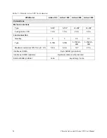
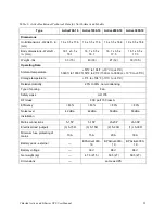
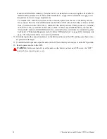
manner until all GND terminals, (-) terminals and (+) terminals are connected together. See Table 10,
“Minimum Requirements for E-Series UPS Installation,” on page 40 for minimum wire gage, wire
temperature and screw torque requirements.
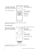
For models E101 and E203, first remove the connection plate from the rear of the battery cabinet.
Next, connect the wires from GND terminal on the UPS to GND wire on the battery cabinet, and then
from (-) terminal on the UPS to the (-) terminal on the battery cabinet. Finally, connect (+) terminal
on the UPS to the (+) terminal on the battery cabinet. Connect any additional battery cabinets in a
“daisy-chain” manner until all GND terminals, (-) terminals and (+) terminals are connected together.
See Table 10, “Minimum Requirements for E-Series UPS Installation,” on page 40 for minimum wire
gage, wire temperature and screw torque requirements.
10. Carefully replace the connection plate(s) on the battery cabinet and the UPS, making sure that no wires
are pinched or damaged.
11. Confirm that all input and output breakers on the UPS and battery cabinet(s) are in the OFF position.
12. Restore power source to the UPS.
WARNING:
Make sure that all circuit breakers on the battery cabinet and UPS are in the“OFF”
postion before removing any covers.

