background image

www.chipsee.com

www.chipsee.com

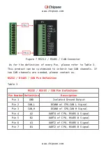
Pin 8

TXD2

UART1 of CPU,RS232 TXD Signal

Pin 9

RXD2

UART1 of CPU,RS232 RXD Signal

Pin 10

TXD1

UART0 of CPU, RS232 TXD Signal

Pin 11

RXD1

UART0 of CPU,RS232 RXD Signal

Pin 12

+5V

5V Power Output, No more than

1A Current output

The RS485 and CAN channels may be customized by Chipsee to the
following arrangements: 

2 x RS485, 1 x CAN(Default)
1 x RS485, 2 x CAN

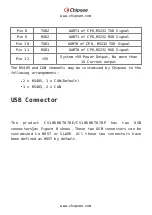
USB Connector

The  product  CS10600T070E/CS10600T070P  has  two  USB
connectors,as Figure 8 shows. These two USB connectors can be
customized  to  HOST  or  SLAVE.  All  these  two  connectors  have
been defined as HOST by default.

Содержание CS10600T070E-C211

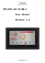
Страница 1: ...www chipsee com www chipsee com PPC EPC A8 70 HB C User Manual Release 1 0...

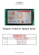
Страница 2: ...ipsee com www chipsee com Chipsee Products Naming Rules CS10600T070E C211 CS10600T070P C211 CS Chipsee Product Abbreviate 10 Horizontal Resolution 80 Means 800 Pixel 10 Means 1024 Pixel 12 Means 1280...

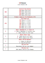
Страница 3: ...ch 070 Means 7 0 Inch 080 Means 8 0 Inch 097 Means 9 7 Inch 101 Means 10 1 Inch 104 Means 10 4 Inch E Means Embedded PC or Panel PC E Means Embedded PC without Case P Means Panel PC with Case C Means...

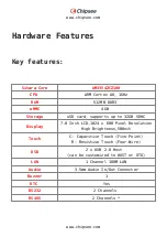
Страница 4: ...rage uSD card supports up to 32GB SDHC Display 7 0 Inch LCD 1024 x 600 Pixel Resolution High Brightness 500nit Touch C Capacitive Touch Five Point R Resistive Touch Four Wire USB 2 x USB 2 0 Host can...

Страница 5: ...A max Power Consumption 6W Typical Working Temperature 20 C to 70 C OS Android TI Linux Debian Angstrom Dimension CS10600T070E C211 190 x 107 8 x 29mm CS10600T070P C211 206 x 135 x 29 8mm Weight CS106...

Страница 6: ...www chipsee com www chipsee com Figure 1 Top View Figure 2 Back View...

Страница 7: ...www chipsee com www chipsee com CS10600T070P C211 Figure 1 Top View...

Страница 8: ...ut DC 6 42V And the total power consumption is normally around 6W The Power Input Connector is 3 pin 3 81mm Screw Terminal connector as Figure 5 Power Input Connector and Figure 4 Back View It is labe...

Страница 9: ...escriptions about the connector definition a CS10600T070E b CS10600T070P Figure 5 Power Input Connector Table 1 Power Input Pin Definition Pin Number Definition Description Pin 1 Positive Input Connec...

Страница 10: ...As Figure 6 shows Figure 6 Capacitive Touch Connector Attention Capacitive touch is very sensitive to power noise Ripple voltage current from the power adapter will cause the LCD ripples and will als...

Страница 11: ...od can eliminate the problem totally The user can also use another method to test this problem Touch the GND of CS10600T070E C211 by one hand the other hand operates on the Capacitive Touch Screen In...

Страница 12: ...hannels are needed please contact us RS232 RS485 CAN Pin Definition Table 3 RS232 RS485 CAN Pin Definition Pin Number Definition Description Pin 1 GND Isolated Ground Output Pin 2 CAN_L DCAN0 of CPU C...

Страница 13: ...2 5V System 5V Power Output No more than 1A Current output The RS485 and CAN channels may be customized by Chipsee to the following arrangements 2 x RS485 1 x CAN Default 1 x RS485 2 x CAN USB Connect...

Страница 14: ...0600T070E b CS10600T070P Figure 8 USB connector Please note The OTG Connector P14 USB0 is defined as HOST by default If it s needed to be defined as SLAVE OTG please Remove two 0603 package 0 Ohm resi...

Страница 15: ...LAN Connector The product CS10600T070E CS10600T070P features one channel 100Mbit Ethernet The connector can be found on the PCB labelled as P13 as Figure 9 LAN Connector shows a CS10600T070E b CS1060...

Страница 16: ...in Figure 10 the uSD card connector is labelled as P5 on the PCB The device supports uSD cards up to 32GB a CS10600T070E b CS10600T070P Figure 11 TF Card uSD Connector Please note The uSD card Slot i...

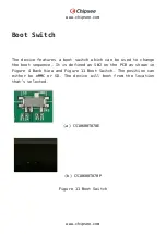
Страница 17: ...hich can be used to change the boot sequence It is defined as SW2 on the PCB as shown in Figure 4 Back View and Figure 11 Boot Switch The position can either be eMMC or SD The device will boot from th...

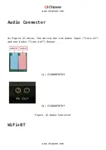
Страница 18: ...www chipsee com www chipsee com Audio Connector As Figure 12 shows the device has one Audio Input Line in and one Audio Line out Output a CS10600T070E b CS10600T070P Figure 12 Audio Connector WiFi BT...

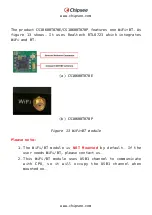
Страница 19: ...Realtech RTL8723 which integrates WiFi and BT a CS10600T070E b CS10600T070P Figure 13 WiFi BT module Please note The WiFi BT module is NOT Mounted by default If the 1 user needs WiFi BT please contact...

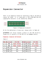
Страница 20: ...nsion Connector As for the definition of every pin please refer to Table 4 ATTENTION All these signals connect to the CPU directly Please use it carefully or the CPU will be damaged easily Expansion C...

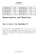
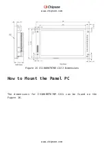
Страница 21: ...8 AIN5 B8 19 AIN6 A8 20 AIN7 C9 Measurements and Mounting How to Mount the Embedded PC The dimensions for CS10600T070E C211 can be found on the Figure 15 The CS10600T070E can be mounted using the 4 sc...

Страница 22: ...www chipsee com www chipsee com Figure 15 CS10600T070E C211 Dimensions How to Mount the Panel PC The dimensions for CS10600T070P C211 can be found on the Figure 16...

Страница 23: ...material is 8mm Make sure the Panel PC is configured correctly The Boot 1 Switch is sitting inside the housing To use it the Panel PC has to be unmounted from the panel For more info see chapter uSD...

Страница 24: ...www chipsee com www chipsee com...

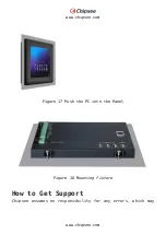
Страница 25: ...www chipsee com www chipsee com Figure 17 Push the PC into the Panel Figure 18 Mounting fixture How to Get Support Chipsee assumes no responsibility for any errors which may...
Страница 26: ...the right to alter the hardware software and or specifications detailed herein at any time without notice and does not make any commitment to update the information contained herein Chipsee products a...

Отзывы: