07
NM1 Series Moulded Case Circuit Breaker
Breaker
min
=
150mm
H
H1
30.5
D
45
°
Hinge
53
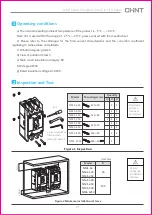
Diagram of handle
installation opening
Φ36
2X
Φ
5.5
≥
200
Φ
78
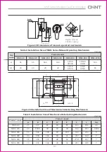
Figure 15 Dimensions of manual operated mechanism
NM1-63
NM1-125
NM1-250
NM1-400
NM1-630
NM1-800
NM1-1250
Size
code
Product model
H
H1
51
20
53
20
56.5
20
100
20
3P:90
4P:100
3P:100
4P:90
103
18
Table 4 Installation Size of NM1 Series Manual Operating Mechanism
Unit: mm
3P:18
4P:20
3P:20
4P:18
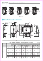
Figure 16
Installation Size of Mechanical Interlocking Mechanism
Switch A
Switch B
B
F
D
E
L
A
C
A
8X
Φ
d
A
B
C
D
E
F
L
Φ
d
Product model
Product model
NM1-63
NM1-125
NM1-250
NM1-400
NM1-630
NM1-800
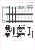
Table 5 Installation Size of Mechanical Interlocking Mechanism
Unit: mm
25
30
35
44
58
70
117
130.5
126
194
200
243
83
90
100
136
172
168
30
30
30
30
48
28
83
90
100
41
62
42
135
155
165
257
270.5
280
186
210
240
330
412
448
4.5
4.5X6
5
7
7
7


