. 1 9 .
. 1 8 .
7.1 Installation
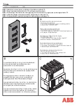
7.1.1 Unload the breaker from the soleplate of package. If it is drawout type, firstly pull out the handle under the drawer-base of breaker, and
plug it into the hole on central part of plastic cover under the drawer-base crossbeam, anticlockwise turns the handle,body will slowly slide
along the outside of drawer-base. When the guide rod points to separated position and handle can't be rotated any longer, pull out the
handle and firmly grasp the aluminum handle on drawer-base, pull out the breaker body and remove it form the base, then move the base
from the soleplate and clean up the dirty things inside the drawer-base.
7.
Installation
Possible positions
7.1.4 Put the breaker (fixed-type) or drawer-base (drawout-type) into the installation-bracket, and make it fixed, directly connect the cable wire of
main circuit to the bus wire of fixed-type circuit breaker. Alternatively put breaker body onto the slideway of drawer-base. Plug the handle
into installation hole, clockwise turns it until the under-part of drawer-base points at the connection position and
“
click
”
sound is heard. It indicates
that breaker body has been connected to its place, then connect the cable of main circuit to drawer-base.
Mounting the circuit-breaker
It is important to distribute the weight of the device uniformily over a rigid mounting surface such as rails or a base plate.
This mounting plane should be perfectly flat (tolerance on support flatness: 2 mm).This eliminates any risk of deformation which could interfere
with correct operation of the circuit breaker.
NA1 devices can also be mounted on a vertical plane using the special brackets.
7.1.2 Check the insulation resistance with a 500V megger, resistance should not be less than 20M
Ω
when ambient temperature is 20
℃±
5
℃
and
relative humidity is 50%~70%. Otherwise dry it.
7.1.3 Power supply
NA1 devices can be supplied either from the top or from the bottom without reduction in performance, in order to facilitate connection
when installed in a switchboard.
Air Circuit Breaker
7.1.5 Partitions
Sufficient openings must be provided in partitions to ensure
good air circulation around the circuit breaker;Any partition
between upstream and downstream connections of the device
must be made of nonmagnetic material.
For high-currents, of 2500 A and upwards, the metal supports or
barriers in the immediate vicinity of a conductor must be made of
non-magnetic material A;Metal barriers through which a conductor
passes must not form a magnetic loop.
Mounting with vertical brackets
Mounting on rails
Busbars
The mechanical connection must be exclude the possibility of
formation of a magnetic loop around a conductor
non magnetic material
A:non magnetic material
A
7.1.6 Busbar connections
The busbars should be suitably adjusted to ensure the connection points are positioned on the terminals before the bolts are inserted
B The connections are held by the supporter which is fixed to the framework of the switchboard, in this way the circuit breaker terminals do
not have to support its weight C. (This support should be placed close to the terminals).
A
B
C
B
Содержание NA1-1000
Страница 1: ...2007 2008 Catalogue Air Circuit Breaker ...
Страница 4: ......
Страница 5: ...Air Circuit Breaker ...
Страница 8: ... 2 1 3 4 5 6 7 8 11 12 13 14 15 Air Circuit Breaker ...


