background image

QMP1MB

Installation Instructions

6

Attaching Accessories to Mobile Stand

WARNING:

EXCEEDING MAXIMUM WEIGHT CAPACITY

MAY LEAD TO SERIOUS PERSONAL INJURY OR
DAMAGE TO EQUIPMENT!  It is the installer’s responsibility
to ensure the total amount of weight placed on the stand
does not exceed 150 lbs (68.04 kg).

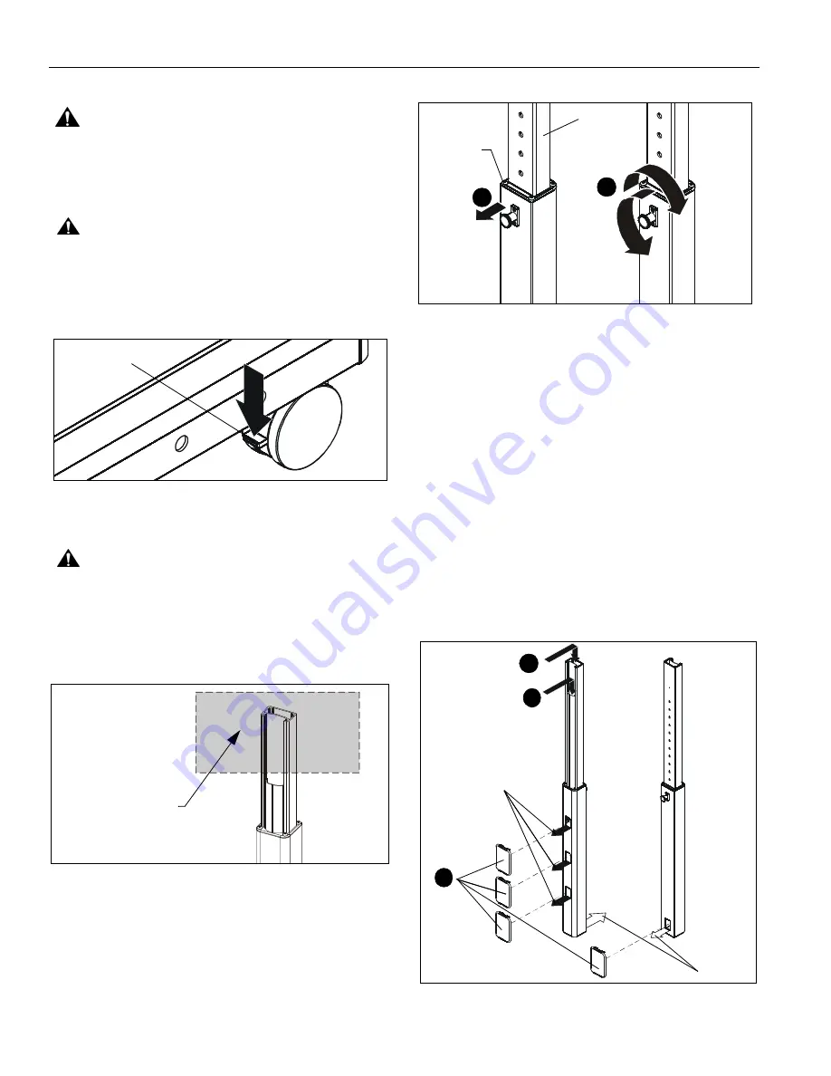
CAUTION:

Before attaching accessories to stand set the

brakes on the back wheels by pressing down on the tab.
(See Figure 5)

1.

Attach accessory and component(s) to stand following
instructions included with the accessory.

Figure 5

Adjusting Stand Height

CAUTION:

ALWAYS remove components attached to

accessories BEFORE adjusting the height of stand.

1.

Firmly grasp

top

 of

inner

 column. (See Figure 6)

IMPORTANT ! :

Firmly grasp at the

top

 of the

inner

column when adjusting stand height. (See Figure 6)

Figure 6

2.

Adjust the stand to the desired height by slightly lifting the
accessory, pulling out knob on the center post and turning
90

o

 in either direction to disengage the locking mechanism.

(See Figure 7)

3.

Raise or lower the upright, then turn the knob 90

o

 either

direction to engage the knob and lock the stand at desired
height. (See Figure 7)

Figure 7

IMPORTANT ! :

Set the height of the stand so the

accessories do NOT rest on the upper part of the outer column.
(See Figure 7) Always set the height so the knob is engaged in
a hole in the inner column.

Cable Management

1.

Signal cables can be run down the front flap of the upright
and out the front of the upright at any of the openings.
(See Figure 8)

2.

Any accessory power cords can be run through the front
and down through the upright to exit out the back.  (See
Figure 8)

3.

Install the snap-on covers (C) to any opening that is not
being used. (See Figure 8)

4.

To remove the snap-on covers, grip the sides of the cover
in the middle and pull off. They can also be removed by
inserting a flat-blade screwdriver into the bottom slot and
rotating the screwdriver.

Figure 8

Press down to
set brakes

Grasp

top of inner

column (within shaded
area) when adjusting
stand height

Do NOT let

2

3

Inner
Column

accessory
rest here

2

(Rear view
of column)

(Front view
of column)

Exit for
power
cables

1

3

Exits for
signal cables

(C)

Содержание QMP1MB

Страница 1: ...I N S T A L L A T I O N I N S T R U C T I O N S Mobile Base Music Stand QMP1MB ...

Страница 2: ...s injury or death if you do not follow the instructions CAUTION A CAUTION alerts you to the possibility of damage or destruction of equipment if you do not follow the corresponding instructions WARNING Failure to read thoroughly understand and follow all instructions can result in serious personal injury damage to equipment or voiding of factory warranty It is the installer s responsibility to mak...

Страница 3: ...have de bocas Chiave a punte aperte Steeksleutel Clé à fourche By Hand A mano Von Hand Com a mão A mano Met de hand À la main Hex Head Wrench Llave de cabeza hexagonal Sechskantschlüssel Chave de cabeça sextavada Chiave esagonale Zeskantsleutel Clé à tête hexagonale Pencil Mark Marcar con lápiz Stiftmarkierung Marcar com lápis Segno a matita Potloodmerkteken Marquage au crayon Drill Hole Perforar ...

Страница 4: ... 4 TOOLSREQUIREDFORINSTALLATION PARTS 3 16 included A 1 E 1 F 1 J 4 5 16 18 x 3 4 K 4 5 16 18 x 2 3 4 L 4 5 16 18 x 4 1 4 M 4 5 16 C 4 D 2 Left leg B 1 Right leg 3 16 3 16 G 1 H 1 Snap on cover End cap Upright Cross bracket Drill bit ...

Страница 5: ...ie tab to loosen and remove cable tie from around knob post See Figure 2 NOTE Disengage knob on upright BEFORE attaching base to the upright 2 Lift up slightly on the inner column of upright and hold firmly toward top of upright See Figure 2 3 Pull out knob on the upright and turn 90 in either direction to disengage the locking mechanism See Figure 2 4 Raise the inner column and turn the knob 90 i...

Страница 6: ...ng mechanism See Figure 7 3 Raise or lower the upright then turn the knob 90o either direction to engage the knob and lock the stand at desired height See Figure 7 Figure 7 IMPORTANT Set the height of the stand so the accessories do NOT rest on the upper part of the outer column See Figure 7 Always set the height so the knob is engaged in a hole in the inner column Cable Management 1 Signal cables...

Страница 7: ...le injury WARNING STAND CAN TIP OVER RESULTING IN RISK OF INJURY Move stand slowly Apply moving force on narrow dimension Never apply force at top always push near middle Push don t pull Figure 9 1 Always place stand on level surface 2 Always lock the wheels when the stand is not moving 3 Check and tighten the hex nuts on the casters occasionally See Figure 10 These should be checked especially af...

Страница 8: ...03 DK Weert Netherlands P 31 0 495 580 852 F 31 0 495 580 845 Asia Pacific A Office No 918 on 9 F Shatin Galleria 18 24 Shan Mei Street Fotan Shatin Hong Kong P 852 2145 4099 F 852 2145 4477 QMP1MB Installation Instructions Chief a products division of Milestone AV Technologies 8800 002907 Rev00 2016 Milestone AV Technologies www milestone com 12 16 ...

Отзывы: