CMA480
Installation Instructions
6
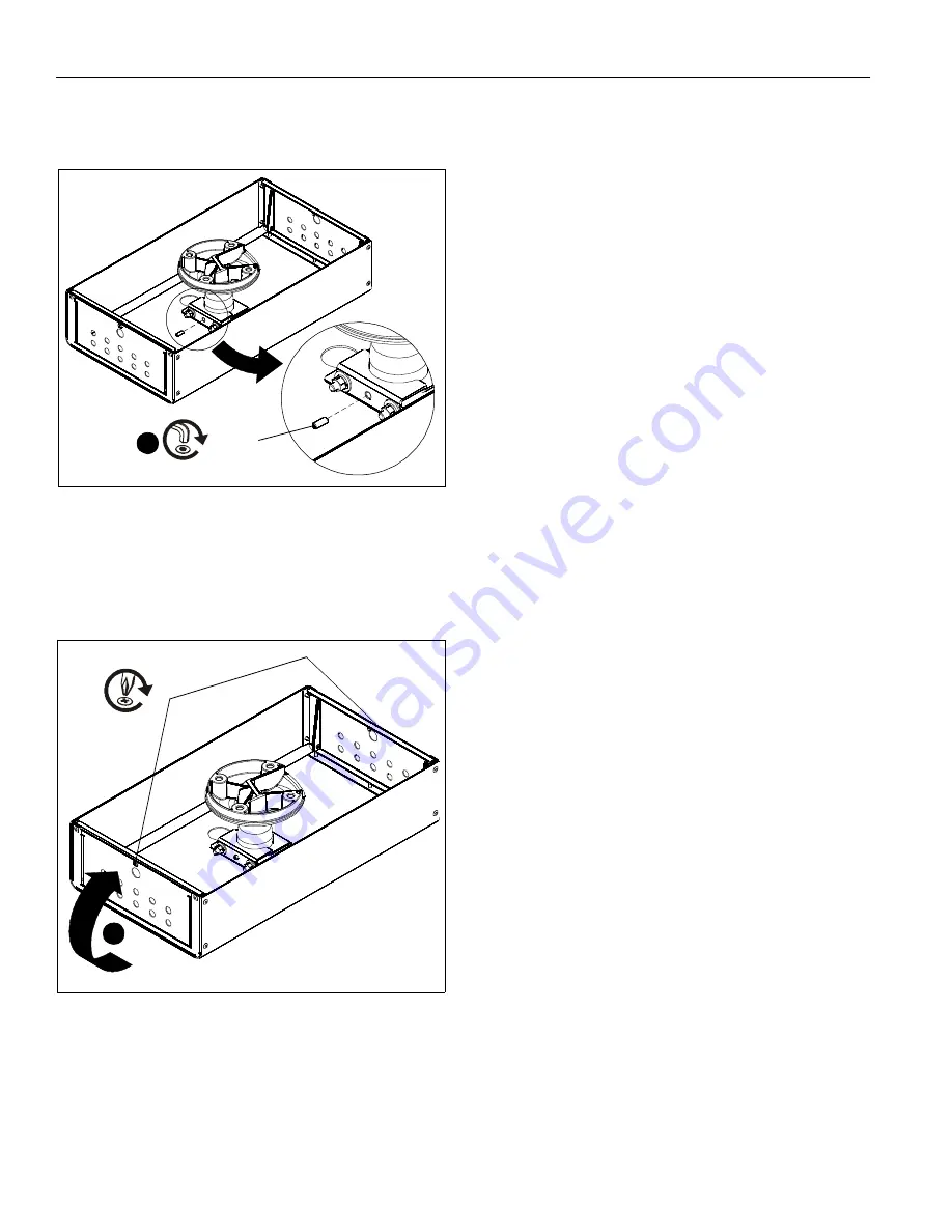
8.
Insert one 1/4-20 x 3/4" set screw (B) into CMA480
enclosure clamp, and tighten against extension column.
(See Figure 5)
Figure 5
9.
Power cords and cables may be run through the cable
management holes. (See Figure 4)
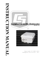
10. Close CMA480 door(s) and secure with screw(s) removed
in Step 3. (See Figure 6)
Figure 6
(B) x 1
8
10
Содержание CMA480
Страница 7: ...Installation Instructions CMA480 7 ...


