background image

SKU 94748        

 for technical questions, please call 1-800-444-3353 

PAGE 13

pLEASE READ THE fOLLOwiNg cAREfuLLy

THE MANUFACTURER AND/OR DISTRIBUTOR HAS PROVIDED THE PARTS LIST AND 
ASSEMBLY DIAGRAM IN THIS MANUAL AS A REFERENCE TOOL ONLY.  NEITHER THE 
MANUFACTURER OR DISTRIBUTOR MAKES ANY REPRESENTATION OR WARRANTY 
OF ANY KIND TO THE BUYER THAT HE OR SHE IS QUALIFIED TO REPLACE ANY 
PARTS OF THE PRODUCT.  IN FACT, THE MANUFACTURER AND/OR DISTRIBUTOR 
EXPRESSLY  STATES THAT  ALL  REPAIRS  AND  PARTS  REPLACEMENTS  SHOULD 
BE  UNDERTAKEN  BY  CERTIFIED  AND  LICENSED TECHNICIANS,  AND  NOT  BY 
THE BUYER.  THE BUYER ASSUMES ALL RISKS AND LIABILITY ARISING OUT OF 
HIS  OR  HER  REPAIRS TO THE  ORIGINAL  PRODUCT  OR  REPLACEMENT  PARTS 
THERETO, OR ARISING OUT OF HIS OR HER INSTALLATION OF REPLACEMENT 
PARTS THERETO.

pARTS LiST

NOTE:

Some parts are listed and shown for illustration purposes only,

and are not available individually as replacement parts.

part

Description

Qty.

1

Washer (C)

2

2

Wave Washer

1

3

Ball Bearing

1

4

Ball Bearing

2

5

Tapping Screw

2

6

Tapping Screw

3

7

Tapping Screw

2

8

Tapping Screw

2

9

Tapping Screw

4

10

Carbon Brush

2

11

Brush Holder

2

12

Epoxy Board

2

13

Plain Washer

1

14

Lock Button

1

15

Power Cord/Plug

1

16

Bearing Holder

1

17

Small Belt Pulley

1

18

Plain Washer

1

19

Plain Washer

1

20

Cord Anchor

1

21

E-Type Ring

1

22

Spring

1

23

Spring

1

24

Spring

1

25

Hex Nut

1

26

Cord Guard

1

27

Power Switch

1

28

Belt Control Plate

1

29

Right Housing

1

30

Front Handle Cover

1

31

Front Handle

1

32

Left Housing

1

33

Mounting Plate

1

part

Description

Qty.

34

Fan Baffle

1

35

Mounting Cover

1

36

Washer (A)

1

37

Plain Washer

3

38

Rivet

1

39

Lever

1

40

Needle Bearing

4

41

Front Pulley Shaft

1

42

Front Pulley

1

43

Rubber Bushing

1

44

Spring

1

45

Ball Bearing

1

46

Gear

1

47

Rear Pulley Shaft

1

48

Large Belt Pulley

1

49

Gear Shaft

1

50

Timing Belt

1

51

Belt Cover

1

52

Middle Housing

1

53

Rotor

1

54

Adjusting Knob

1

55

Lock Knob

1

56

Speed Adjuster

1

57

Bracket Assembly

1

58

Rear Pulley

1

59

Mounting

1

60

Stator

1

61

Internal Wire Assembly

2

63

Internal Wire Assembly

1

64

Tapping Screw

15

65

Vacuum Bag

1

66

Sanding Belt (80 Grit)

1

Содержание 94748

Страница 1: ... website at http www harborfreight com To prevent serious injury read and understand all warnings and instructions before use Copyright 2006 by Harbor Freight Tools All rights reserved No portion of this manual or any artwork contained herein may be reproduced in any shape or form without the express written consent of Harbor Freight Tools For technical questions or replacement parts please call 1...

Страница 2: ... procedures parts list and assembly diagram Keep your invoice with this manual Write the invoice number on the inside of the front cover Keep this manual and invoice in a safe and dry place for future reference GENERAL SAFETY RULES WARNING READ AND UNDERSTAND ALL INSTRUCTIONS Failure to follow all instructions listed below may result in electric shock fire and or serious injury SAVE THESE INSTRUCT...

Страница 3: ... wet conditions Water entering a power tool will increase the risk of electric shock Do not abuse the Power Cord Never use the Power Cord to carry the tools or pull the Plug from an outlet Keep the Power Cord away from heat oil sharp edges or moving parts Replace damaged Power Cords immediately Dam aged Power Cords increase the risk of electric shock When operating a power tool outside use an outd...

Страница 4: ... measures reduce the risk of starting the tool accidentally Store idle tools out of reach of children and other untrained persons Tools are dangerous in the hands of untrained users Maintain tools with care Keep cutting tools sharp and clean Properly main tained tools with a sharp cutting edge are less likely to bind and are easier to control Do not use a damaged tool Tag damaged tools Do not use ...

Страница 5: ...mp or wet location Never leave the Belt Sander unattended when it is plugged into an electrical outlet Turn off the tool and unplug it from its electrical outlet before leaving Industrial applications must follow OSHA guidelines Use clamps or a vise to secure and support the workpiece to a stable platform Holding the workpiece by hand or against your body is unstable and may lead to loss of contro...

Страница 6: ...an result in eye skin and breathing irritation Always use a NIOSH approved respirator and safety goggles Avoid skin exposure Proper ventilation of the work area is required WARNING The warnings and cautions discussed in this manual cannot cover all possible conditions and situations that may occur It must be understood by the operator that common sense and caution are factors which cannot be built...

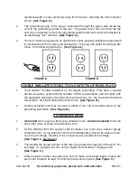
Страница 7: ...em which satisfies OSHA requirements and complies with the applicable standards of Underwriters Laboratories Inc the Canadian Standard Association and the National Electrical Code See Figure B Double insulated tools may be used in either of the 120 volt outlets shown in the preceding illustration See Figure B Extension Cords Grounded tools require a three wire extension cord Double Insulated tools...

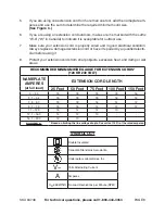
Страница 8: ...d by a qualified electri cian before using it Protect your extension cords from sharp objects excessive heat and damp or wet areas RECOMMENDED MINIMUM WIRE GAUGE FOR EXTENSION CORDS 120 or 240 VOLT NAMEPLATE AMPERES at full load EXTENSION CORD LENGTH 25 Feet 50 Feet 75 Feet 100 Feet 150 Feet 0 2 0 18 18 18 18 16 2 1 3 4 18 18 18 16 14 3 5 5 0 18 18 16 14 12 5 1 7 0 18 16 14 12 12 7 1 12 0 18 14 12...

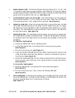
Страница 9: ...and held turns on the Belt Sander To turn off the Sander release pressure on the Power Switch and the switch will automatically return up to its OFF position See Figure E Lock Button 14 The Belt Sander features a Lock Button that allows continu ous operation without constantly holding the Power Switch 27 To lock the Power Switch to its ON position squeeze the Power Switch depress the Lock Button a...

Страница 10: ...ean of sanding de bris and properly installed in the Belt Sander Using dull Sanding Belts will place an excessive load on the Belt Sander and increases the possibility of burning the workpiece To install the Sanding Belt Unplug the Belt Sander from its electrical outlet Lay the Belt Sander down on its side with its Lever 39 facing upward See Figure E Pull out on the Lever 39 See Figure E Insert th...

Страница 11: ...r on the work surface first Then with a forward motion begin sanding as the tool is lowered onto the work surface Move the Belt Sander slowly back and forth across the work surface using short overlapping strokes Do not apply excessive pressure on the Belt Sander Too much pressure will over load the motor and reduce Sanding Belt 66 speed Avoid tilting or rocking the Belt Sander or sanding in one s...

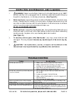
Страница 12: ...mmerse any electrical part of the tool in any liq uids CAUTION All maintenance service or repairs not mentioned in this manual must only be performed by a qualified service technician 1 2 3 4 5 TROUBLESHOOTING Problem Possible Solution Belt Sander will not turn on Make sure to firmly squeeze the Power Switch Make sure the Power Cord Plug is connected to a working 120 volt grounded electrical outle...

Страница 13: ...er 1 3 Ball Bearing 1 4 Ball Bearing 2 5 Tapping Screw 2 6 Tapping Screw 3 7 Tapping Screw 2 8 Tapping Screw 2 9 Tapping Screw 4 10 Carbon Brush 2 11 Brush Holder 2 12 Epoxy Board 2 13 Plain Washer 1 14 Lock Button 1 15 Power Cord Plug 1 16 Bearing Holder 1 17 Small Belt Pulley 1 18 Plain Washer 1 19 Plain Washer 1 20 Cord Anchor 1 21 E Type Ring 1 22 Spring 1 23 Spring 1 24 Spring 1 25 Hex Nut 1 ...

Страница 14: ...own for illustration purposes only and are not available individually as replacement parts 65 Vacuum Bag not shown 66 Sanding Belt not shown 64 29 27 14 44 56 6 28 52 20 5 26 15 61 63 35 16 18 3 9 11 10 12 53 33 13 17 7 60 34 32 49 4 2 48 50 8 51 54 22 1 21 43 58 37 23 36 57 39 38 30 25 31 24 19 55 41 40 42 59 45 47 46 ...

Страница 15: ...ncidental or consequential damages so the above limitation of exclusion may not apply to you This warranty is expressly in lieu of all other warranties express or implied including the warranties of merchantability and fitness To take advantage of this warranty the product or part must be returned to us with trans portation charges prepaid Proof of purchase date and an explanation of the complaint...

Страница 16: ...n Le Copyright 2006 par le Harbor Freight Tools Tous droits réservés Aucune portion de ce manuel ou de n importe quel travail d art contenu ici ne peut être reproduite dans aucun forme ou manière sans le consentement écrit explicite de Harbor Freight Tools Pour les questions techniques ou les pièces détachées appelez vous s il vous plaît 1 800 444 3353 IMPORTANT Cette édition de langue française e...

Страница 17: ...l inspection la maintenance et le nettoyage des procédures la liste de pièces et le diagramme de montage Gardez votre facture avec ce manuel Écrivez le nombre de facture sur l intérieur de la couverture première Gardez ce manuel et facture dans un coffre fort et un endroit sec pour la référence future RÈGLES RÉPANDUES DE SÉCURITÉ AVERTISSEMENT LISEZ ET COMPRENEZ TOUTES LES INSTRUCTIONS L échec de ...

Страница 18: ...courant murale inverse la prise de courant S il ne va pas toujours contactez un électricien qualifié pour installer une prise de courant murale polarisée Ne changez pas la prise de courant de toute façon L isolation double élimine le besoin pour le trois fil a mis le cordon de pouvoir à la terre et a mis le système d alimentation électrique à la terre Évitez le contact de corps avec les surfaces m...

Страница 19: ...e pouvoir peuvent s ensuivre dans la blessure personnalisée Ne pencher pas Gardez la position nécessaire et l équilibre à tous moments La position nécessaire et l équilibre permettent le meilleur contrôle de l instrument de pouvoir dans les situations inattendues Utilisez l équipement de sécurité Portez toujours la protection d oeil Le mas que de filtre les chaussures de sécurité antidérapantes le...

Страница 20: ...ment par le personnel de répa ration qualifié Entretien ou la maintenance exécutée par le personnel disqualifié pourrait s ensuivre dans un risque de blessure En assurant l entretien d un instrument utilisez des pièces détachées seule ment identiques Suivez des instructions dans L inspection la Maintenance et le Nettoyage section de ce manuel L utilisation de pièces faites sans autori sation ou d ...

Страница 21: ...les deux mains N utilisez pas la Ponceuse de Ceinture s il a été baissé fait tort laissé dehors ou plongé dans le liquide Pour éviter le choc électrique ne manipulez pas la Ponceuse de Ceinture ou sa Prise de courant de Cordon de Pouvoir avec les mains mouillées Assurez vous que la pièce de fabrication est libre des ongles et d autres objets étrangers qui peuvent faire tort à l instrument et ou le...

Страница 22: ...et les situations qui peuvent se produire Il doit être compris par l opérateur que le sens commun et la prudence sont des facteurs qui ne peuvent pas être introduits dans ce produit mais doivent être fournis par l opérateur SAUVEZ CES INSTRUCTIONS INSTALLER À LA TERRE WARNING Improperly connecting the grounding wire can result in the risk of electric shock Check with a qualified electrician if you...

Страница 23: ...ls ont un système d isolation double spécial qui satisfait des exigences OSHA et se plie aux normes applicables d Underwriters Laboratories Inc l Association Standard canadienne et le Code Électrique national Voir l Image B Les instruments isolés doubles peuvent être utilisés dans n importe laquelle des prises de courant murale de 120 volts montrées en illustration précédente Voir l Image B Cordon...

Страница 24: ...rrectement télégraphié et dans la bonne condition électrique Remplacez toujours un cordon d extension fait tort ou faites le réparer par un électricien qualifié avant le fait de l utiliser Protégez vos cordons d extension des objets pointus la chaleur excessive et les régions humides ou mouillées CALIBREMÉTALLIQUEMINIMALRECOMMANDÉPOURLESCORDONSD EXTENSION 120 Ou 240 volts PLAQUE AMPÈRES à la plein...

Страница 25: ...la Ponceuse de Ceinture Pour éteindre la Ponceuse la pression de déclenchement sur l Interrupteur de Pouvoir et l interrupteur reviendra automatiquement jusqu à sa position ÉTEINTE Voir l Image E Le Bouton 14 de Serrure La Ponceuse de Ceinture présente un Bouton de Serrure qui permet l opération continue sans constamment tenir l Interrupteur de Pouvoir 27 Pour fermer l Interrupteur de Pouvoir à so...

Страница 26: ...rrectement installé dans la Ponceuse de Ceinture L utilisation des Ceintures pour le fait d éroder émoussées placera une charge excessive sur la Ponceuse de Ceinture et augmente la possibilité de brûler la pièce de fabrication Installer la Ceinture pour le fait d éroder Débranchez la Ponceuse de Ceinture de sa prise de courant murale électrique Posez la Ponceuse de Ceinture sur son côté avec son L...

Страница 27: ...de la Ponceuse de Ceinture sur la surface de travail d abord Alors avec un mouvement avancé commencez à éroder comme l instrument est baissé sur la surface de travail Déplacez la Ponceuse de Ceinture lentement ça et là à travers la surface de travail en utilisant des coups courts chevauchants N appliquez pas de pression excessive sur la Ponceuse de Ceinture Trop de pres sion surchargera le moteur ...

Страница 28: ...peut affecter son opération sûre Si le bruit anormal ou la vibration se produisent faites corriger le problème avant l utilisation de plus N utiliser pas l équipement fait tort Avant chaque utilisation Inspectez la Ceinture pour le fait d éroder 66 L utilisa tion des Ceintures pour le fait d éroder émoussées causera l usure excessive du moteur de la Ponceuse de Ceinture et ne produira pas de résul...

Страница 29: ...de Ceinture ou éroder dans un endroit trop de long La ceinture pour le fait d éroder s enlève des rouleaux pendant l utilisation Réglez l alignement de la Ceinture pour le fait d éroder L Interrupteur de Pouvoir n éteindra pas la Ponceuse de Ceinture Débranchez la Ponceuse de Ceinture de sa prise de courant murale électrique Arrêtez l utilisation de la Ponceuse de Ceinture et ayez un technicien d ...

Страница 30: ...Plaque de Contrôle de Ceinture 1 29 Boîtier Droit 1 30 Couverture de Poignée Première 1 31 Poignée Première 1 32 Boîtier Gauche 1 33 Le fait d Installer la Plaque 1 Pièce Description Quantité 34 Le Fan Désoriente 1 35 Le fait d Installer la Couverture 1 36 Rondelle A 1 37 Rondelle Simple 3 38 Rivet 1 39 Levier 1 40 Palier d aiguille 4 41 Arbre de Poulie Premier 1 42 Poulie Première 1 43 Entretoise...

Страница 31: ...r le fait d éroder non montrée 64 29 27 14 44 56 6 28 52 20 5 26 15 61 63 35 16 18 3 9 11 10 12 53 33 13 17 7 60 34 32 49 4 2 48 50 8 51 54 22 1 21 43 58 37 23 36 57 39 38 30 25 31 24 19 55 41 40 42 59 45 47 46 NOTEZ Quelques pièces sont énumérées et montrées pour les buts d illustration seulement et ne sont pas en vente individuellement comme les pièces détachées ...

Страница 32: ...uestions techniques appelez vous s il vous plaît 1 800 444 3353 Français 94748 Page 17 GARANTIE 3491 Mission Oaks Blvd PO Box 6009 Camarillo CA 93011 800 444 3353 Déférez au texte anglais pour l explication de garantie ...

Отзывы: