background image

SKU 91062

PAGE 13

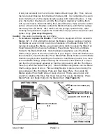
the wood stock.  Then, transfer pressure to the Rear Base Plate, and continue
planing slowly to the end of the cut.  

Do not pull the Planer back over the surface

already cut.  

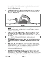
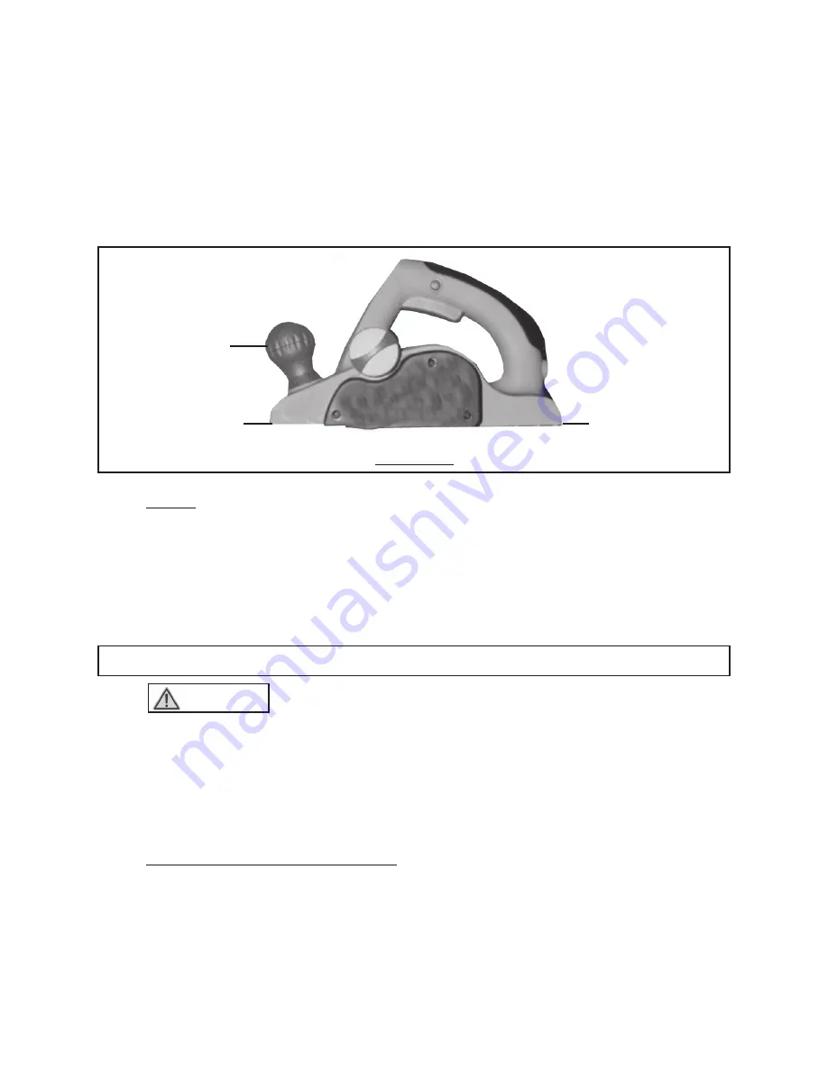
(See Figure G.)

6.

If necessary, repeat Step #5, using progressively deeper cuts until you near the
desired depth.  Then, readjust the Depth Knob (48) to make a light cut for the
final pass.  

(See Figure G.)

FRONT BASE PLATE

(54)

REAR BASE PLATE

(61)

DEPTH KNOB

(48)

FIGURE G

7.

NOTE:

  The Planer’s Motor may stall if the tool is improperly used.  If the Motor

begins to stall, reduce the feed speed at which you are making the cut and/or
reduce the depth of the cut.

8.

When finished planing, release pressure on the Trigger (16) and the Planer will
automatically stop.  Wait until Planer blade comes to a complete stop.  Then
unplug the Planer from its electrical outlet, and store the Planer in a safe, clean,
dry location.

INSPECTION, MAINTENANCE, AND CLEANING

1.

        WARNING! 


Always unplug the Planer from its electrical outlet before

performing any inspection, maintenance, cleaning, or changing accesso-
ries.

2.

Before each use,

 inspect the general condition of the Planer.  Check for mis-

alignment or binding of moving parts, cracked or broken parts, damaged wiring,
and any other condition that may affect its safe operation.  If abnormal noise or
vibration occurs, have the problem corrected before further use.

Do not use damaged equipment.

3.

To replace the Motor Carbon Brushes:

  It may become necessary at some-

time to replace or clean the

 two Carbon Brushes (36) when the Motor perfor-

mance decreases, or stops working completely.  The Carbon Brushes are located
on the side of the Right Motor Housing (45).  To do so, use a standard screw-

Содержание 91062

Страница 1: ... 3491 Mission Oaks Blvd Camarillo CA 93011 Visit our Web site at http www harborfreight com Copyright 2003 by Harbor Freight Tools All rights reserved No portion of this manual or any artwork contained herein may be reproduced in any shape or form without the express written consent of Harbor Freight Tools For technical questions please call 1 800 444 3353 ...

Страница 2: ...r work area clean and well lit Cluttered benches and dark areas invite accidents 2 Do not operate power tools in explosive atmospheres such as in the presence of flammable liquids gases or dust Power tools create sparks which may ignite the dust or fumes SKU 91062 PAGE 2 REV 02 04 Item Description Electrical Requirements 120V 60 Hz 5 5 AMPs 16 500 RPM No Load or 33 000 Cuts Per Minute Polarized 2 ...

Страница 3: ...ne way If the plug does not fit fully in the outlet reverse the plug If it still does not fit contact a qualified electrician to install a polarized outlet Do not change the plug in any way Double insulation eliminates the need for the three wire grounded power cord and grounded power supply system 6 Avoid body contact with grounded surfaces such as pipes radiators ranges and refrigerators There i...

Страница 4: ...at the rate for which it is designed 16 Do not use the power tool if the Power Switch does not turn it on or off Any tool that cannot be controlled with the Power Switch is dangerous and must be replaced 17 Disconnect the Power Cord Plug from the power source before making any adjustments changing accessories or storing the tool Such preventive safety measures reduce the risk of starting the tool ...

Страница 5: ...t in the risk of electric shock Check with a qualfified electrician if you are in doubt as to whether the outlet is properly grounded Do not modify the power cord plug provided with the tool Never remove the grounding prong from the plug Do not use the tool if the power cord or plug is damaged If damaged have it repaired by a service facility before use If the plug will not fit the outlet have a p...

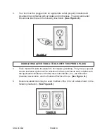
Страница 6: ...TED TOOLS TOOLS WITH TWO PRONG PLUGS 4 Tools marked Double Insulated do not require grounding They have a special double insulation system which satisfies OSHA requirements and complies with the applicable standards of Underwriters Laboratories Inc the Canadian Standard Association and the National Electrical Code See Figure B 5 Double insulated tools may be used in either of the 120 volt outlets ...

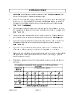
Страница 7: ... one extension cord for more than one tool add the nameplate amperes and use the sum to determine the required minimum cord size See Figure C 6 If you are using an extension cord outdoors make sure it is marked with the suffix W A W in Canada to indicate it is acceptable for outdoor use 7 Make sure your extension cord is properly wired and in good electrical condition Always replace a damaged exte...

Страница 8: ...nreadable or missing contact Harbor Freight Tools for a replacement 3 Ground this product To comply with the National Electric Code and to provide additional protection from the risk of electrical shock this product should only be connected to a 120 volt electrical outlet that is protected by a Ground Fault Circuit Interrupter GFCI 4 Never plug the Power Cord of this product into an electrical out...

Страница 9: ... not attempt to use this product 14 Industrial applications must follow OSHA requirements 15 Maintain this product with care Keep this product clean and dry for better and safer performance Also make sure to keep the Blades sharp 16 Maintenance For your safety service and maintenance should be performed regularly by a qualified technician 17 Check for damaged parts Before using this product carefu...

Страница 10: ...e using this product Operation of electrical equipment in close proximity to a heart pacemaker could cause interference or failure of the pacemaker WARNING Some dust created by power sanding planing sawing grind ing drilling and other construction activities contain chemicals known to the State of California to cause cancer birth defects or other reproductive harm Some examples of these chemicals ...

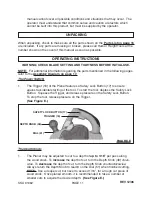
Страница 11: ...s manual as soon as possible manual cannot cover all possible conditions and situations that may occur The operator must understand that common sense and caution are factors which cannot be built into this product but must be supplied by the operator FIGURE E TRIGGER 16 SAFETY LOCK BUTTON 17 DEPTH KNOB 48 DIAL 51 The Depth Knob 1 The Planer may be adjusted to cut to a depth of up to 1 16 per pass ...

Страница 12: ...unplugged from its 120 volt grounded electrical outlet Then make any necessary adjustments to the cutting depth and cutting width of the Planer See Figures E and F 2 Whenever possible use clamps a vise or other safe practical ways to hold and support the wood stock 3 While standing to the side of the wood stock hold the Planer firmly with one hand on the handle portion of the Housing 15 45 and the...

Страница 13: ...il Planer blade comes to a complete stop Then unplug the Planer from its electrical outlet and store the Planer in a safe clean dry location INSPECTION MAINTENANCE AND CLEANING 1 WARNING Always unplug the Planer from its electrical outlet before performing any inspection maintenance cleaning or changing accesso ries 2 Before each use inspect the general condition of the Planer Check for mis alignm...

Страница 14: ...nd wrench to loosen the three Hex Head Screws 60 that secure the Blades Press Blade Plate 56 and Blade Holder to the Blade Shaft 63 Slide the Blades lengthwise out of the Blade Shaft using a piece of wood to avoid cuts to your fingers Once the Blades have been removed clean the Blades Press Blade Plate Blade Holder and the Blade Shaft thoroughly before installing the reversed or new Blades to allo...

Страница 15: ...R SHE IS QUALIFIED TO REPLACE ANY PARTS OF THE PRODUCT IN FACT THE MANUFACTUER AND OR DISTRIBUTOR EXPRESSLY STATES THAT ALL REPAIRS AND PARTS REPLACEMENTS SHOULD BE UNDERTAKEN BY CERTIFIED AND LICENSED TECHNICIANS AND NOT BY THE BUYER THE BUYER ASSUMES ALL RISK AND LIABILITY ARISING OUT OF HIS OR HER REPAIRS TO THE ORIGINAL PRODUCT OR REPLACEMENT PARTS THERETO OR ARISING OUT OF HIS OR HER INSTALLA...

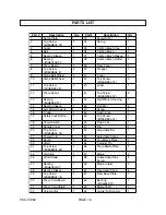
Страница 16: ...ring Sleeve 1 46 Nut M5 4 15 Left Motor Housing 1 47 Screw 1 16 Trigger 1 48 Depth Knob 1 17 Safety Lock Button 1 49 Tap Screw 8SEABB04 14 1 18 Power Switch 1 50 Plug Cock 1 19 Handle Cover 1 51 Dial 1 20 Tap Screw 8SEABB04 18 2 52 Adjustable Nut 1 21 Power Cord 1 53 Adjustable Spring 1 22 Spring 1 54 Front Base Plate 1 23 Stator 1 55 Cylinder Pin 1 24 Tap Screw 8SEABB04 60 2 56 Press Blade Plate ...

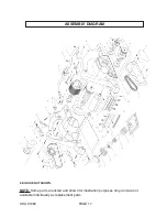
Страница 17: ...SKU 91062 PAGE 17 17 16 18 ASSEMBLY DIAGRAM NOTE Some parts are listed and shown for illustration purposes only and are not available individually as replacement parts 68 GUIDE NOT SHOWN ...

Отзывы: