7A-44 AUTOM ATIC TRANSM ISSION
TURBO HYDRA-MATIC 4 0 0 /4 7 5 TRANSMISSION
INDEX
General Description....................................................... 7A-44
Theory of Operation...................................................... 7A-45
Hydraulic System - Functions of Values and
Hydraulic Control U nit................................................. 7A-45
Hydraulic Oil System................................................... 7A-54
Maintenance and Adjustment..................................... 7A-72
Checking Transmission M ount................................. 7A-72
Transmission Fluid....................................................... 7A-72
Column Shift Linkage Adjustment......................... 7A-73
Detent Switch Adjustment.......................................... 7A-74
Neutral Start Backup Lamp Switch Adjustment. 7A-74
Service Operations........................................................... 7A-75
Pressure Regulator Valve............................................ 7A-75
Control Valve Body...................................................... 7A-75
G overnor............................................................................ 7A-75
Modulator and Modulator Valve.............................. 7A-75
Parking Linkage - 10, 20 Series.............................. 7A-76
Rear Seal.......................................................................... 7A-76
Other Service Operations............................................ 7A-76
Transmission Replacement......................................... 7A-76
Diagnosis............................................................................. 7A-77
Sequence for Diagnosis............................................... 7A-77
Oil Checking Procedure..............................................
Oil Leak Diagnosis....................................................... 7A-77
Oil Pressure Check........................................................ 7A-78
Case Porosity R epair.................................................... 7A-78
Vacuum Modulator Diagnosis................................... 7A-78
Manual Linkage............................................................. 7A-80
Trouble Diagnosis.......................................................... 7A-80
Special Tools...................................................................... 7A-87-88
GENERAL DESCRIPTION
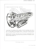
The Turbo Hydra-Matic 400/475 transmission is a fully
automatic unit consisting primarily of a 3-element
hydraulic torque converter and a compound planetary
gear set. Three multiple-disc clutches, one gear unit, one
roller clutch, and two bands provide the friction elements
required to obtain the desired function of the compound
planetary gear set.
The torque converter couples the engine to the planetary
gears through oil and provides hydraulic torque
multiplication when required. The compound planetary
gear set produces three forward speeds and reverse.
The 3-element torque converter consists of a pump or
driving member, a turbine or driven member, and a
stator assembly. The stator is mounted on a one-way
roller clutch which will allow the stator to turn clockwise
but not counter-clockwise.
The torque converter housing is filled with oil and is
attached to the engine crankshaft by a flex plate and
always rotates at engine speed. The converter pump is an
integral part of the converter housing, therefore the
pump blades, rotating at engine speed, set the oil within
the converter into motion and direct it to the turbine,
causing the turbine to rotate.
As the oil passes through the turbine it is traveling in
such a direction that if it were not re-directed by the
stator it would hit the rear of the converter pump blades
and impede its pumping action. So at low turbine speeds,
the oil is re-directed by the stator to the converter pump
in such a manner that it actually assists the converter
pump to deliver power or multiply engine torque.
As turbine speed increases, the direction of the oil
leaving the turbine changes and flows against the rear
side of the stator vanes in a clockwise direction. Since
the stator is now impeding the smooth flow of oil, its
roller clutch releases and it revolves freely on its shaft.
Once the stator becomes inactive, there is no further
multiplication of engine torque within the converter. At
this point, the converter is merely acting as a fluid
coupling as both the converter pump and turbine are
being driven at approximately the same speed - or at
one-to-one ratio.
A hydraulic system pressurized by a gear type pump
provides the working pressure required to operate the
friction elements and automatic controls.
External control connections to transmission are:
Manual Linkage - To select the desired operating
range.
Engine Vacuum - To operate a vacuum modulator
unit.
12 Volt Electrical - To operate an electrical detent
solenoid.
A vacuum modulator is used to automatically sense any
change in the torque input to the transmission. The
vacuum modulator transmits this signal to the pressure
regulator for line pressure control, to the 1-2 accumulator
valve, and to the shift valves so that all torque
requirements of the transmission are met and smooth
shifts are obtained at all throttle openings.
The detent solenoid is activated by an electric switch on
the carburetor. When the throttle is fully opened, the
switch on the carburetor is closed, activating the detent
solenoid and causing the transmission to downshift for
passing speeds.
The selector quadrant has six selector positions: P, R, N,
D, L2, LI.
P. PARK position positively locks the output shaft to
the transmission case by means of a locking pawl to
LIGHT DUTY TRUCK SERVICE MANUAL
Содержание Light Duty Truck 1973
Страница 1: ......
Страница 4: ......
Страница 6: ......
Страница 39: ...HEATER AND AIR CONDITIONING 1A 13 Fig 14 Heater Wiring Diagrams LIGHT DUTY TRUCK SERVICE MANUAL...
Страница 53: ...HEATER AND AIR CONDITIONING 1A 27 LIGHT DUTY TRUCK SERVICE MANUAL...
Страница 115: ...LIGHT DUTY TRUCK SERVICE M A N U A L HEATER AND AIR CONDITIONING 1A 89...
Страница 123: ...BODY 1B 3 Fig 6 Typical 06 Van LIGHT DUTY TRUCK SERVICE MANUAL...
Страница 149: ...BODY 1B 29 Fig 84 Body Mounting 06 Fig 85 Body Mounting 14 LIGHT DUTY TRUCK SERVICE MANUAL...
Страница 171: ...LIGHT DUTY TRUCK SERVICE M A N U A L Fig 2 Frame Horizontal Checking Typical FRAME 2 3...
Страница 173: ...LIGHT DUTY TRUCK SERVICE M A N U A L Fig 4 10 30 Series Truck Frame FRAME 2 5...
Страница 174: ...2 6 FRAME LIGHT DUTY TRUCK SERVICE MANUAL Fig 5 Underbody Reference Points G Van...
Страница 177: ...LIGHT DUTY TRUCK SERVICE MANUAL G 10 20 C 10 P 10 30 Fig 2 Front Suspension C P K Typical FRONT SUSPENSION 3 3...
Страница 185: ...FRONT SUSPENSION 3 11 Fig 16 Toe out on Turns LIGHT DUTY TRUCK SERVICE MANUAL...
Страница 224: ......
Страница 229: ...REAR SUSPENSION AND DRIVELINE 4 5 Fig 13 Rear Spring Installation C K Models LIGHT DUTY TRUCK SERVICE MANUAL...
Страница 266: ......
Страница 310: ...5 44 BRAKES C MODELS G MODELS P MODELS Fig 77 Parking Brake System LIGHT DUTY TRUCK SERVICE MANUAL...
Страница 351: ...ENGINE 6 15 Fig ID Sectional View of Eight Cylinder Engine LIGHT DUTY TRUCK SERVICE MANUAL...
Страница 375: ...EN G IN E 6 39 LIGHT DUTY TRUCK SERVICE MANUAL...
Страница 376: ...6 4 0 ENGINE LIGHT DUTY TRUCK SERVICE MANUAL...
Страница 377: ...ENG IN E 6 41 LIGHT DUTY TRUCK SERVICE MANUAL...
Страница 378: ...LIGHT DUTY TRUCK SERVICE MANUAL Fig 37L K Series Engine Front Mount 6 42 ENG INE...
Страница 379: ...E N G IN E 6 43 FRONT MOUNT REAR MOUNT Fig 38L G Series Engine Mounts LIGHT DUTY TRUCK SERVICE MANUAL...
Страница 400: ...6 6 4 ENG INE LIGHT DUTY TRUCK SERVICE MANUAL...
Страница 401: ...ENG IN E 6 65 LIGHT DUTY TRUCK SERVICE MANUAL...
Страница 402: ...6 6 6 ENGINE LIGHT DUTY TRUCK SERVICE MANUAL...
Страница 403: ...E NG IN E 6 67 Fig 36V C Series Engine Mounts LIGHT DUTY TRUCK SERVICE MANUAL...
Страница 410: ......
Страница 423: ...EN G IN E C OOLING 6K 13 Fig 16 Overheating Chart LIGHT DUTY TRUCK SERVICE MANUAL...
Страница 424: ...6 K 1 4 ENG INE COOLING Fig 17 Coolant Loss Chart LIGHT DUTY TRUCK SERVICE MANUAL...
Страница 455: ...ENGINE FUEL 6M 31 Fig K13 Accelerator Controls P30 42 454 Engine LIGHT DUTY TRUCK SERVICE MANUAL...
Страница 456: ...6M 32 ENGINE FUEL Fig K15 Accelerator Controls G Van L 6 LIGHT DUTY TRUCK SERVICE MANUAL...
Страница 492: ......
Страница 506: ...CEC PLUNGER IS EXTENDED Fig lid Vacuum Advance Diagram Six Cylinder Engine 6T 14 EMISSION CONTROL SYSTEMS...
Страница 512: ...Fig 18e Vacuum Advance Diagram V8 Engine...
Страница 515: ...EMISSION CONTROL SYSTEMS 6T 23 Fig If Six Cylinder A I R System LIGHT DUTY TRUCK SERVICE MANUAL...
Страница 516: ...6 T 2 4 E M IS S IO N CONTROL SYSTEMS LIGHT DUTY TRUCK SERVICE MANUAL...
Страница 517: ...E M IS S IO N C O N TR O L SYSTEM S 6T 25 Fig 4f Diverter Valve Vent Valve LIGHT DUTY TRUCK SERVICE MANUAL...
Страница 528: ......
Страница 540: ...6 Y 1 2 ENGINE ELECTRICAL Fig 16b Battery Installation C K Series LIGHT DUTY TRUCK SERVICE MANUAL...
Страница 572: ...6Y 44 ENGINE ELECTRICAL Fig 25i V 8 Spark Plug Wire Installation LIGHT DUTY TRUCK SERVICE MANUAL...
Страница 590: ......
Страница 592: ...7M 2 CLUTCHES MANUAL TRANSMISSIONS VIEW B Fig la Clutch Linkage Assy C K Models LIGHT DUTY TRUCK SERVICE MANUAL...
Страница 593: ...CLUTCHES MANUAL TRANSMISSIONS 7M 3 LIGHT DUTY TRUCK SERVICE MANUAL...
Страница 594: ...7M 4 CLUTCHES MANUAL TRANSMISSIONS Fig lc Clutch Linkage Assy P Models LIGHT DUTY TRUCK SERVICE MANUAL...
Страница 598: ...7M 8 CLUTCHES MANUAL TRANSMISSIONS LIGHT DUTY TRUCK SERVICE MANUAL...
Страница 642: ......
Страница 654: ......
Страница 656: ...LIGHT DUTY TRUCK SERVICE MANUAL Fig 19M Drive Range Low First Gear Typical 7A 14 AUTOMATIC T R A N S M IS S IO N...
Страница 662: ...LIGHT DUTY TRUCK SERVICE M A N U A L Fig 22M LI Range Manual First Gear Typical 7A 20 AUTOMATIC TRANSMISSION...
Страница 668: ...LIGHT DUTY TRUCK SERVICE M A N U A L Fig 25M Reverse Range Typical 7A 26 AUTOMATIC T R A N S M IS S IO N...
Страница 739: ...FUEL TANKS AND EXHAUST 8 9 Fig 15 Filler Neck and Vent Hose Van LIGHT DUTY TRUCK SERVICE MANUAL...
Страница 740: ...8 10 FUEL TANKS AND EXHAUST Fig 16 Fuel Feed and Return Pipes Front C K LIGHT DUTY TRUCK SERVICE MANUAL...
Страница 743: ...FUEL TANKS AND EXHAUST 8 13 LIGHT DUTY TRUCK SERVICE MANUAL...
Страница 744: ...8 14 FUEL TANKS AND EXHAUST LIGHT DUTY TRUCK SERVICE MANUAL...
Страница 746: ...8 16 FUEL TANKS AND EXHAUST Fig 2 5 Fuel Feed Pipe Front P 105 4 2 LIGHT DUTY TRUCK SERVICE MANUAL...
Страница 760: ...8 30 FUEL TANKS AND EXHAUST Fig 40 Exhaust Pipe P Models LIGHT DUTY TRUCK SERVICE MANUAL...
Страница 761: ...FUEL TANKS AND EXHAUST 8 31 LIGHT DUTY TRUCK SERVICE MANUAL...
Страница 763: ...FUEL TANKS AND EXHAUST 8 33 LIGHT DUTY TRUCK SERVICE MANUAL...
Страница 766: ......
Страница 781: ...STEERING 9 15 OIL PRESSURE OIL RETURN PORT VALVE BODY Fig 21 Left Turn Position LIGHT DUTY TRUCK SERVICE MANUAL...
Страница 832: ...LIGHT DUTY TRUCK SERVICE MANUAL Fig 106 Power Steering Pump Mounting Typical 9 66 STEERING...
Страница 833: ...PUMP ASSEMBLY STEERING GEAR TYPICAL SMALL V8 TYPICAL LARGE V8 STEERING 9 67...
Страница 860: ...9 94 STEERING LEAKAGE AREAS Fig 133 Power Steering Gear Leakage LIGHT DUTY TRUCK SERVICE MANUAL...
Страница 861: ...STEERING 9 95 Fig 134 Power Steering Pump Leakage LIGHT DUTY TRUCK SERVICE MANUAL...
Страница 864: ......
Страница 876: ......
Страница 886: ...11 10 CHASSIS SHEET METAL LIGHT DUTY TRUCK SERVICE MANUAL...
Страница 891: ...ELECTRICAL BODY AND CHASSIS 12 5 LIGHT DUTY TRUCK SERVICE MANUAL...
Страница 897: ...ELECTRICAL BODY AND CHASSIS 12 11 Fig 14 Instrum ent Cluster Assembly C K Models LIGHT DUTY TRUCK SERVICE MANUAL...
Страница 934: ......
Страница 942: ......
Страница 970: ......
Страница 972: ......
Страница 974: ......
Страница 976: ...V...
Страница 978: ......
Страница 979: ......


