background image

down bolts to specification. See TORQUE SPECIFICATIONS.

         Removal & Installation (1.8L)

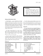
         1) Fuel pump is located in fuel tank and is integral with

fuel sending unit assembly. Relieve fuel pressure. See

FUEL SYSTEM PRESSURE RELEASE (GASOLINE). Disconnect negative battery

cable. Remove rear seat cushion. Remove 4 fuel sending unit assembly

access panel bolts and remove access panel. Disconnect harness

connector from fuel sending unit assembly.

         2) Remove fuel pipe from top of fuel sending unit assembly.

Remove 8 fuel sending unit assembly hold-down bolts and remove hold-

down plate. Remove fuel sending unit assembly and "O" ring from fuel

tank.

         3) Remove No. 2 fuel sending unit support and rubber cushion.

Remove fuel pressure regulator. Remove fuel pump strainer hold-down

clip and remove fuel pump strainer.

         4) Remove No. 1 fuel sending unit support from fuel sending

unit plate. Remove No. 1 fuel filter cushion from fuel filter.

Disconnect harness connector from fuel pump. Remove fuel pump from

fuel filter.

         5) To install, reverse removal procedure. Use NEW "O" ring on

fuel pressure regulator and fuel sending unit assembly. Tighten fuel

sending unit assembly hold-down bolts to specification. See

TORQUE SPECIFICATIONS.

         Removal & Installation (3.0L)

         1) Fuel pump is located in fuel tank and is integral with

fuel sending unit assembly. Relieve fuel system pressure. See

CRANKSHAFT (24X) POSITION SENSOR (DIS). Disconnect negative battery

cable.

         2) Raise and support vehicle. Disconnect fuel lines and

harness connections at fuel tank. Remove fuel tank. Remove fuel

sending unit assembly cam lock ring. Lift fuel sending unit assembly

from fuel tank.

         3) Disconnect fuel pump harness connector and hose clamp.

Push in release tabs on fuel pump and lift off sending unit assembly.

To install, reverse removal procedure using NEW "O" ring and gasket.

         Removal & Installation (4.6L)

         1) Disconnect negative battery cable. Relieve fuel system

pressure. See CRANKSHAFT (24X) POSITION SENSOR (DIS). Raise and

support vehicle. Remove the fuel sender assembly.

         2) Remove fuel tank pressure sensor. Disconnect fuel pump

electrical connector. Remove fuel level sensor electrical connector

retaining clip. Remove fuel pump.

         3) Push in release tabs on fuel pump and lift off sending

unit assembly. To install, reverse removal procedure using NEW "O"

ring and gasket.

         FUEL PRESSURE REGULATOR (GASOLINE)

NOTE:    On 3.0L, fuel pressure regulator and fuel rail are serviced

         as an assembly only. DO NOT remove pressure regulator or

         pressure regulator cover from fuel rail.

         See FUEL RAIL & INJECTORS.

         Removal (1.3L)

         Relieve fuel pressure. See

FUEL SYSTEM PRESSURE RELEASE (GASOLINE). Disconnect negative battery

cable. Disconnect pressure regulator vacuum hose. Remove fuel return

line from pressure regulator. Remove pressure regulator screws. Remove

pressure regulator from fuel rail. Remove fuel inlet "O" ring from

pressure regulator.

Содержание 2001 Camaro

Страница 1: ...er of VIN INTRODUCTION CAUTION When battery and some PCM input devices are disconnected vehicle computer and memory systems may lose memory data Driveability problems may exist until computer systems...

Страница 2: ...ct throttle and cruise control cables Remove boost pressure manifold and vacuum block Remove cable bracket and tensioner bracket to supercharger mounting stud NOTE Tensioner bracket to supercharger st...

Страница 3: ...static proof package before opening Do not touch electrical terminals of components unless properly grounded Do not lay electrical components on car seat carpeting or dashboard Use electrostatic prot...

Страница 4: ...nect harness connectors from PCM Remove PCM mounting bolts if equipped Remove PCM To install reverse removal procedure Transfer any necessary components i e knock sensor module etc to new PCM before i...

Страница 5: ...eads in exhaust manifold or pipe 2 Disconnect negative battery cable Remove front floor console Pull back passenger side carpet from along console floor area Disconnect oxygen sensor electrical connec...

Страница 6: ...nsor 1 1 Ensure oxygen sensor is free of contaminants DO NOT use cleaning solvents of any type Oxygen sensor may be difficult to remove when engine temperature is less than 120 F 48 C Excessive remova...

Страница 7: ...n Exhaust Manifold Sensor 2 On Exhaust Pipe 3 1L Sensor 1 On Exhaust Manifold Sensor 2 On Exhaust Pipe 3 4L Sensor 1 On Exhaust Manifold Sensor 2 On Exhaust Pipe 3 5L Sensor 1 On Exhaust Manifold Sens...

Страница 8: ...Fig 2 Locating Heated Oxygen Sensors Catera Courtesy of General Motors Corp...

Страница 9: ...Fig 3 Locating Bank 1 Sensor 1 Heated Oxygen Sensor 5 7L Camaro Firebird Courtesy of General Motors Corp...

Страница 10: ...Locating Bank 1 Sensor 2 Heated Oxygen Sensor 5 7L Camaro Firebird Courtesy of General Motors Corp Fig 5 Locating Bank 2 Sensor 1 Heated Oxygen Sensor 5 7L Camaro Firebird Courtesy of General Motors...

Страница 11: ...Fig 6 Locating Bank 2 Sensor 2 Heated Oxygen Sensor 5 7L Camaro Firebird Courtesy of General Motors Corp Fig 7 Locating Bank 1 Sensor 1 Heated Oxygen Sensor Corvette Courtesy of General Motors Corp...

Страница 12: ...ating Bank 1 Sensor 2 Bank 2 Sensor 2 Heated Oxygen Sensors Corvette Courtesy of General Motors Corp Fig 9 Locating Bank 2 Sensor 1 Heated Oxygen Sensor Corvette Courtesy of General Motors Corp COOLIN...

Страница 13: ...ck 2 Start engine With pressure cap removed idle engine until normal operating temperature is reached Close air bleed screw when coolant is visible dripping from bleed screw With engine still idling a...

Страница 14: ...coolant recovery tank mounting nuts Move coolant recovery tank aside Remove camshaft position sensor mounting bolt and remove camshaft position sensor To install reverse removal procedure Tighten cams...

Страница 15: ...nsor mounting bolt nut and remove crankshaft position sensor 2 Inspect crankshaft position sensor O ring for wear cracks or other damage Replace as necessary Lubricate NEW O ring with engine oil befor...

Страница 16: ...ENSOR DIS Removal Installation 3 1L 3 4L 1 Disconnect negative battery cable Remove serpentine belt from crankshaft pulley Raise and support vehicle 2 Remove crankshaft harmonic balancer bolt Using Ba...

Страница 17: ...k Remove 6 screws retaining coils to ignition control module Remove ignition coils from module 2 Remove screws and washers securing ignition control module to bracket Remove ignition control module To...

Страница 18: ...m assembly from engine 2 Remove 4 coil housing to cover screws Remove housing cover Remove coil harness connector from module Remove module to cover screws Remove module from cover NOTE DO NOT wipe gr...

Страница 19: ...emoval Installation 2 2L Disconnect negative battery cable Remove air cleaner outlet resonator Disconnect knock sensor electrical connector Remove knock sensor To install reverse removal procedure Tig...

Страница 20: ...iate article in ENGINES Disconnect knock sensor electrical connector Remove knock sensor To install reverse removal procedure Tighten knock sensor to specification See TORQUE SPECIFICATIONS FUEL SYSTE...

Страница 21: ...tighten at this time On 1 3L and 1 8L remove fuel pump relay On all models start and run engine until it stalls Crank starter for 3 seconds to remove remaining fuel from fuel lines Turn ignition off...

Страница 22: ...trainer This will restrict fuel flow Removal Installation Except 1 3L 1 8L 3 0L 4 6L 1 Fuel pump is located in fuel tank and is integral with fuel sending unit assembly Fuel pump must be replaced with...

Страница 23: ...fuel system pressure See CRANKSHAFT 24X POSITION SENSOR DIS Disconnect negative battery cable 2 Raise and support vehicle Disconnect fuel lines and harness connections at fuel tank Remove fuel tank R...

Страница 24: ...ing clip If retaining clip is damaged fuel tank must be replaced Retaining clip cannot be serviced separately 2 Unlatch fuel line bundle retaining clip on left side of fuel tank Disconnect EVAP purge...

Страница 25: ...ve and discard filter screen if dirty Installation To install reverse removal procedure DO NOT reuse O ring Lubricate NEW fuel inlet O ring with oil and install into regulator Replace filter screen as...

Страница 26: ...e fuel tank Disconnect fuel tank pressure sensor electrical connector Remove fuel tank pressure sensor To install reverse removal procedure Removal Installation 1 8L Relieve fuel system pressure See C...

Страница 27: ...r Remove 3 intake manifold brace bolts and remove brace from engine Disconnect harness connectors from injectors 2 Disconnect fuel pressure regulator vacuum hose Disconnect and plug fuel feed hose fro...

Страница 28: ...rail on intake manifold Push down on fuel rail to seat injectors into manifold Tighten fuel rail retaining bolts to specification See TORQUE SPECIFICATIONS To complete installation reverse removal pro...

Страница 29: ...ation reverse removal procedure using NEW fuel supply line plastic retainers Removal 2 4L 1 Relieve fuel pressure See FUEL SYSTEM PRESSURE RELEASE GASOLINE Disconnect negative battery cable Remove air...

Страница 30: ...Ventilation PCV air tube from cam cover Disconnect PCV valve from cam cover Remove fuel rail bracket retainer nut Disconnect fuel injector electrical connectors from each fuel injector Lay harness as...

Страница 31: ...necessary to gain access to fuel rail and fuel lines Remove electrical harness from routing clips on fuel rail 3 Remove fuel line retaining bolt Disconnect harness connectors from injectors Remove fu...

Страница 32: ...Fig 15 Locating Fuel Rail Assembly Components 1 9L VIN 7 Shown VIN 8 Is Similar Courtesy of General Motors Corp...

Страница 33: ...Fig 16 Locating Fuel Rail Assembly Components 2 2L VIN F Courtesy of General Motors Corp Fig 17 Locating Fuel Rail Assembly Components 2 2L VIN 4 Courtesy of General Motors Corp...

Страница 34: ...Fig 18 Locating Fuel Rail Assembly Components 2 4L VIN T Courtesy of General Motors Corp Fig 19 Locating Fuel Rail Assembly Components 3 0L VIN R Courtesy of General Motors Corp...

Страница 35: ...Fig 20 Locating Fuel Rail Assembly Components 3 1L VIN M 3 4L VIN E Courtesy of General Motors Corp...

Страница 36: ...Fig 21 Locating Fuel Rail Assembly Components 3 5L VIN H Courtesy of General Motors Corp Fig 22 Locating Fuel Rail Assembly Components 3 8L VIN K Courtesy of General Motors Corp...

Страница 37: ...Fig 23 Locating Fuel Rail Assembly Components 3 8L VIN 1 Courtesy of General Motors Corp Fig 24 Locating Fuel Rail Assembly Components 4 0L VIN C 4 6L VIN Y 9 Courtesy of General Motors Corp...

Страница 38: ...5 7L Courtesy of General Motors Corp IDLE AIR CONTROL VALVE CAUTION For calibration purposes several different style Idle Air Control IAC valves are used Ensure replacement valve has the same part num...

Страница 39: ...1 8L Remove throttle body assembly See THROTTLE BODY Drain any remaining engine coolant Remove 4 IAC valve screws and remove IAC valve from throttle body assembly Install NEW rubber gasket onto throt...

Страница 40: ...d support vehicle Disconnect hoses from charcoal canister filter Remove charcoal canister filter attaching bolts Remove charcoal canister filter To install reverse removal procedure Tighten bolts to s...

Страница 41: ...8 1 8L 13 18 1 9L 1 2 2L Cavalier Sunfire 18 25 Saturn 2 2 4L 19 26 3 1L 3 4L 3 8L 2 Harmonic Balancer Bolt 3 1L 3 4L 76 103 3 8L 3 110 149 Idle Air Control IAC Valve Bolt 1 8L 14 18 5 Ignition Contro...

Страница 42: ...e Flange Bolt 80 9 Fuel Filter Pressure Regulator Bracket Nut Corvette 40 4 5 Fuel Pressure Regulator Screw 1 3L 71 106 8 12 1 9L 71 8 2 2L Cavalier Sunfire 53 6 Saturn 44 5 2 4L 84 9 5 3 1L 3 4L 75 8...

Страница 43: ...etaining Bolt 2 2L Cavalier Sunfire 58 6 5 Saturn 89 10 2 4L 58 6 5 3 5L 89 10 3 8L 89 10 4 0L 4 6L 5 7L 106 12 Throttle Position TP Sensor Screw 1 3L 1 9L 3 1L 3 4L 3 8L 5 7L 18 2 1 8L 31 3 5 2 2L 2...

Отзывы: