E N G IN E ELECTRICAL
6Y-9
material, and also a piece of tape over the shaft at
the slip ring end.
CAUTION: Brushes may drop onto the rbtor
shaft and become contaminated with bearing
lubricant. Clean brushes prior to installing with
a non- toxic cleaner such as trichlorethylene or
a soft dry cloth.
4. Remove the stator lead attaching nuts and separate
stator from end frame.
NOTE: At this point, with the two end
frames separated the stator disconnected and
the rotor removed electrical checks of the
rotor, rectifier bridge, stator and diode trio
brush lead clip may be made without further
disassembly. Refer to the specific checks as
outlined in this section.
5. Remove screw attaching diode trio to brush holder
assembly and remove diode trio from end frame
(fig. 1C).
NOTE: Diode trio may be checked for a
grounded brush lead clip at this point. Refer
to diode trio checks.
6. Remove the rectifier bridge attaching screw and the
"BAT" terminal screw, and disconnect the capacitor
lead. Remove rectifier bridge from the end frame.
7. Remove two attaching screws, and remove brush
holder and regulator assemblies.
NOTE: Two insulators are assembled over
the top of the brush retaining clips and the
two screws have special insulating sleeves
over the screw body.
8. Remove retaining screw and capacitor from end of
frame (fig. 6C).
9. Remove slip ring end frame bearing (if necessary).
Refer to bearing replacement covered in this
section.
10. Remove pulley retaining nut and slide washer,
pulley, fan and spacer from shaft.
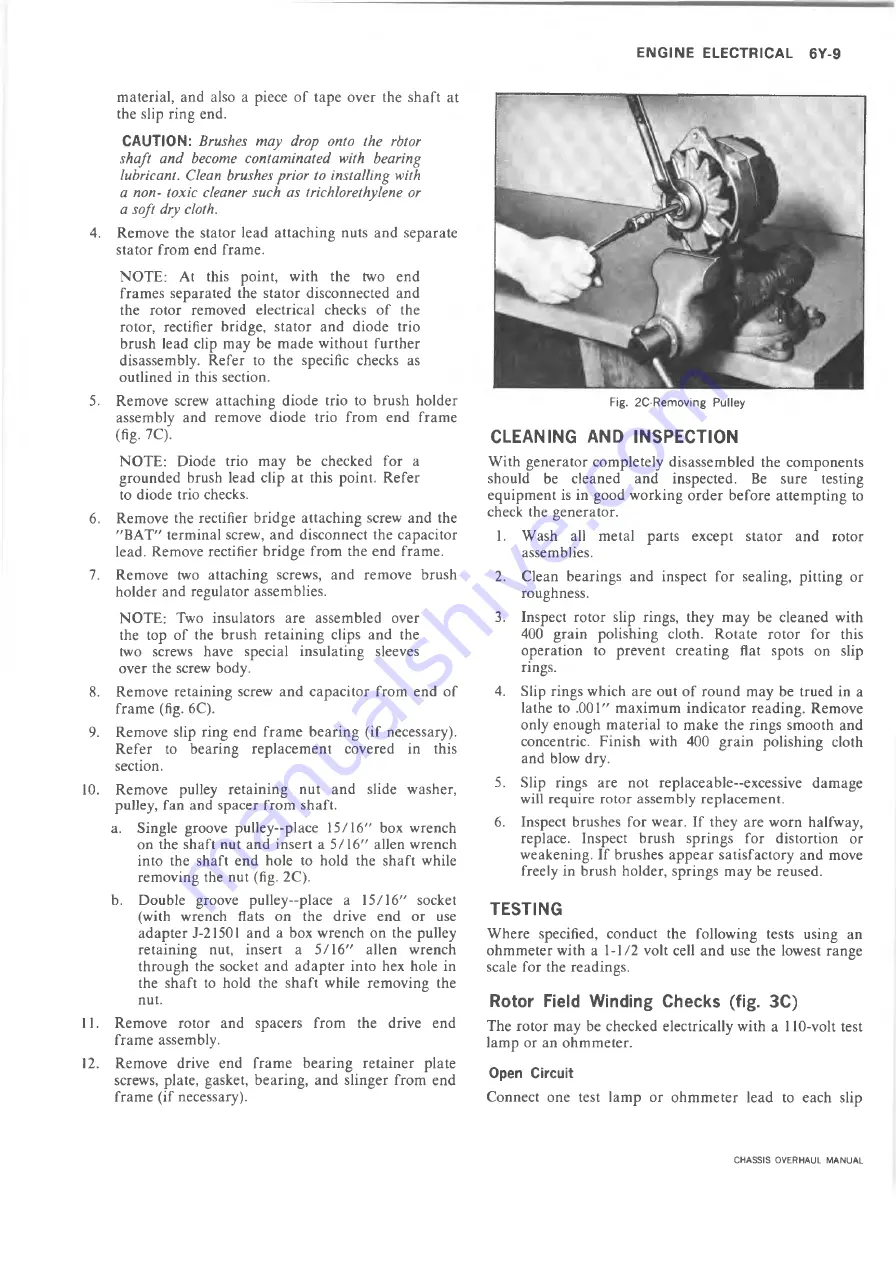
a. Single groove pulley—place 15/16" box wrench
on the shaft nut and insert a 5/16" alien wrench
into the shaft end hole to hold the shaft while
removing the nut (fig. 2C).
b. Double groove pulley—place a 15/16" socket
(with wrench flats on the drive end or use
adapter J-21501 and a box wrench on the pulley
retaining nut, insert a 5/16" alien wrench
through the socket and adapter into hex hole in
the shaft to hold the shaft while removing the
nut.
11. Remove rotor and spacers from the drive end
frame assembly.
12. Remove drive end frame bearing retainer plate
screws, plate, gasket, bearing, and slinger from end
frame (if necessary).
Fig. 2C-Removing Pulley
CLEANING AND INSPEC TIO N
With generator completely disassembled the components
should be cleaned and inspected. Be sure testing
equipment is in good working order before attempting to
check the generator.
1. Wash all metal parts except stator and rotor
assemblies.
2. Clean bearings and inspect for sealing, pitting or
roughness.
3. Inspect rotor slip rings, they may be cleaned with
400 grain polishing cloth. Rotate rotor for this
operation to prevent creating flat spots on slip
rings.
4. Slip rings which are out of round may be trued in a
lathe to .001" maximum indicator reading. Remove
only enough material to make the rings smooth and
concentric. Finish with 400 grain polishing cloth
and blow dry.
5. Slip rings are not replaceable—excessive damage
will require rotor assembly replacement.
6. Inspect brushes for wear. If they are worn halfway,
replace. Inspect brush springs for distortion or
weakening. If brushes appear satisfactory and move
freely in brush holder, springs may be reused.
TESTING
Where specified, conduct the following tests using an
ohmmeter with a 1-1/2 volt cell and use the lowest range
scale for the readings.
Rotor Field Winding Checks (fig. 3C )
The rotor may be checked electrically with a 110-volt test
lamp or an ohmmeter.
Open Circuit
Connect one test lamp or ohmmeter lead to each slip
CHASSIS OVERHAUL MANUAL
Содержание 10 series 1973
Страница 1: ......
Страница 3: ...r...
Страница 5: ......
Страница 21: ......
Страница 31: ......
Страница 34: ...REAR AXLE DIFFERENTIAL CARRIER 4 3 OVERHAUL MANUAL...
Страница 85: ...4 54 REAR AXLE DIFFERENTIAL CARRIER OVERHAUL MANUAL...
Страница 93: ...4 62 REAR AXLE DIFFERENTIAL CARRIER OVERHAUL MANUAL...
Страница 103: ...V...
Страница 141: ...I...
Страница 144: ...ENGINE 6 3 OIL PRESSURE SENDING UNIT Fig 1 In Line Engine Lubrication OVERHAUL MANUAL...
Страница 145: ...6 4 ENGINE FUEL PUMP PUSH ROD OILING OIL FILTER AND BY PASS VALVE Fig 2 Sm all V8 Engine Lubrication OVERHAUL MANUAL...
Страница 179: ......
Страница 185: ...6M 6 CARBURETORS Fig M6 Monojet See Fig M7 for legend...
Страница 219: ...L...
Страница 247: ...7 M 28 CLUTCHES AND MANUAL TRANSMISSIONS Fig 19X Loading Countergear Bearings Fig 20X Loading Mainshaft Pilot Bearings...
Страница 289: ...7M 70 CLUTCHES AND MANUAL TRANSMISSIONS Fig 13F Transfer Case Exploded View OVERHAUL MANUAL...
Страница 352: ...AUTOMATIC TRANSMISSION 7A 49 Fig 85M Planetary Gear Train Exploded View OVERHAUL MANUAL...
Страница 363: ...7A 60 AUTOMATIC TRANSMISSION Fig IT S ide Cross Section Typical OVERHAUL MANUAL...
Страница 457: ......
Страница 459: ......
Страница 522: ......


