


Maintenance and Repair:
The GH-703 Power Riveter has been manufactured to
give maximum service with minimum care. In order that
this may be accomplished, the following recommendations
should be followed:
1. The hydraulic system should be full of oil and free from
air at all times.
2. Keep excessive moisture and dirt out of the air supply
to prevent wear.
3. Do not pound on the rear of the tool head to force
rivets into holes, as this will damage the tool.
4. Make sure the pulling head is correctly and
securely attached.
To fill riveter with oil:
1. Remove head body assembly from handle assembly.
2. Fill handle assembly with automatic transmission fluid
(ATF-Dexron
®
) to within 1/8” of the top of the handle
casting.
3. Replace head body assembly, being sure gasket (55)
and O-ring (56) are properly in place. Tighten cap screws
(57) uniformly to prevent leakage around gasket.
4. Connect tool to air line and cycle ten times to fully
circulate hydraulic system with oil.
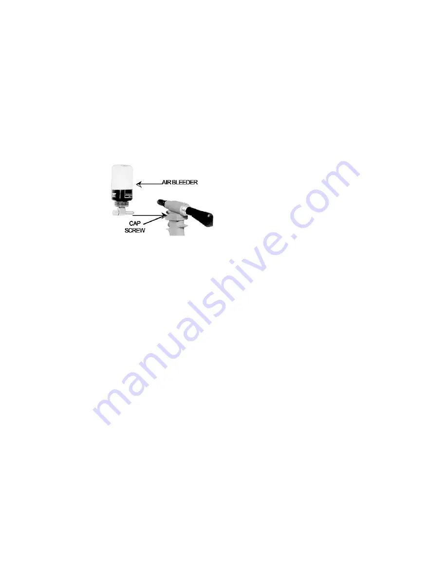
5. With tool connected to the air line, remove cap screw
(16) being sure NOT to cycle tool. Attach Avdel® air
bleeder 700A77 according to instructions included with
bleeder and purge system of air by cycling the tool until oil
flow is free of air bubbles.
6. Remove air bleeder and allow excess oil to drain from
screw hole.
7. Reinstall cap screw (16) and Stat-O-Seal washer (15)
and test tool for proper function by installing rivets.
NOTE: Steps 1 through 4 may be eliminated when replacing
just a small amount of oil.
Troubleshooting:
1. Check air line for correct pressure at the tool. It must
be 90 to 120 psi.
2. Check tool for lack of hydraulic fluid (see oil filling
instructions).
3. Check for oil leakage.
a. Oil leaking around the cap screw (16) in the head
indicates that the screw is loose or the washer gasket
(15) needs replacing.
b. If oil should leak through the bypass hole at the base
of the handle (34), the O-rings (18 or 37) are worn
or damaged.
c.
Oil leakage from the front of the head (1) indicates
that O-rings (2) are worn or damaged.
4. Check for excessive air leakage from air bleed valve.
a. If spring (46) is broken or dislodged, replace per
instructions on page 7.
b. If O-rings (51) on plug (52) are worn or damaged,
replace.
c.
If O-rings (47) on valve spool (48) are worn or damaged,
replace.
5. Check movement of piston (4). If it does not move freely or
is slow in operation:
a. O-rings (2), (5), or (7) may be damaged and require
replacement.
b. Piston (4) may be mechanically locked due to
damaged parts.
c.
Power piston may be held off its seat on rod (43)
allowing oil to bypass. Drain tool, flush thoroughly,
and refill with fresh fluid.
d. Muffler (53) or air filter inside spool (48) may be plugged
with dirt. Clean them thoroughly with normal solvent
and back-blow with compressed air.
e. Hole in metering screw in valve spool (48) may be
blocked or damaged. Hole diameter should be .028”.
Clear and size or replace valve spool.
6. If the tool cycles repeatedly, even though the trigger has
not been pulled, it indicates that the spring (46) which holds the
valve sleeve (45) is broken or dislodged. See air bleed valve
instructions on page 7.
7. If the mandrel sticks in pulling head:
a. Pulling head components need maintenance.
Disassemble pulling head, clean, and replace worn
parts. Reassemble following instructions on page 8.
b. There may be excess oil in front of the head piston.
With tool attached to air line, remove cap screw (16)
and allow excess oil to run out. Replace cap screw
and tighten.
c. The mandrels are wedged side by side in jaw follower
(3)or tube (10) from failure to eject spent mandrel from
tool prior to inserting next rivet. Disassemble pulling
head, clear jaw follower, and reassemble following
instructions on page 8.
8. If the mandrel breaks above designed breaknotch:
a. Jaws (2) are not seating on mandrel properly due to
wear. Replace if worn.
b. Jaws (2) are not seating properly due to worn jaw spring.
Replace if spring is less than 2” long.
5
Содержание GH-703
Страница 5: ...4...


