SR209 Plus Series
│
34
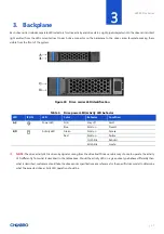
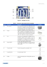
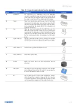
Table 10
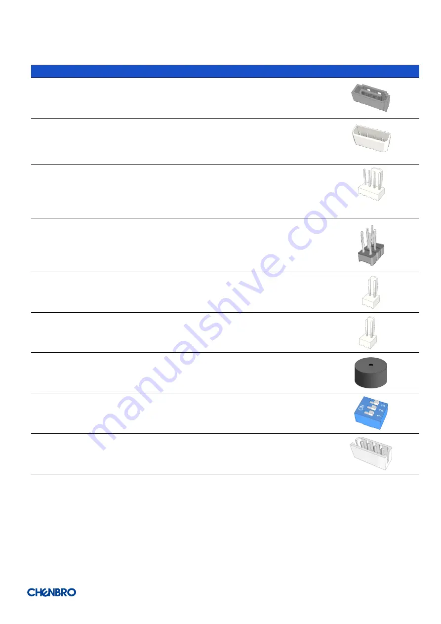
Connector and pin header function description
Label
Description
Description
Drawing
A
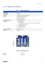
SATA/SAS
For connecting to a mainboard, this 7-pin SATA/SAS
connector is applied. A proper cable selection is essential as
well to make sure good signal integrity can be maintained for
the whole connection path from mainboard HDD devices.
B
Power
These two connectors are used to power four 3.5” hard disks,
connected to this backplane, and each can ensure that all
drives are supplied with stable power inputs. If the chassis fan
is also powered by fan header (JF01), this configuration is
highly recommended.
C
Fan
There are two 4-pin headers for the PWM fan, and it is
alternative solution that the chassis fan can be powered and
monitored by this backplane instead of motherboard. If the
chassis fan is connected to mainboard, user needs to disable
the fan monitoring function of backplane by DIP switch
(SW1).
D
Signal
i
ndicator
The event LED with red/black wire is located on front bezel
of SR209 Plus and can be configured through this pin header.
E
Power fail mute
Transfer mute signal from backplane to PSU
F
Power fail alarm
Send alarm signal to PSU
G
Buzzer
Buzzer will alarm when fan and temperature become
abnormal
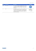
H
DIP switch
The settings of on-board hardware monitor can be controlled
and configured through this DIP switch. It can manage the
functions of PWM fan & Buzzer On/Off.
I
I2C
The motherboard can monitor HDD temperature and fan
status through this connector. However, the I2C connector
on motherboard side is vendor dependent, so please contact
our field application engineers to fully utilize this feature.


