RB13804N4WFT
List of
Figures
│
4
List of Figures
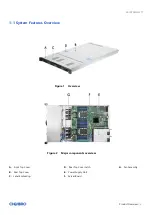
Figure 1
Overview .................................................................................................................................... 8
Figure 2
Major components overview ...................................................................................................... 8
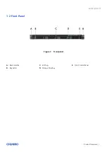
Figure 3
Front panel ................................................................................................................................. 9
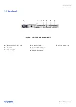
Figure 4
Back panel with redundant PSU ............................................................................................... .10
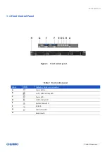
Figure 5
Front control panel ................................................................................................................... 11
Figure 6
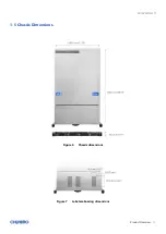
Chassis dimensions ................................................................................................................... 12
Figure 7
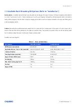
Label embossing dimensions .................................................................................................... 12
Figure 8
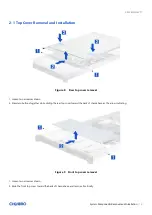
Rear top cover removal ............................................................................................................. 18
Figure 9
Front top cover removal ............................................................................................................ 18
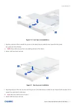
Figure 10 Front top cover installation ...................................................................................................... 19
Figure 11 Rear top cover installation ........................................................................................................ 19
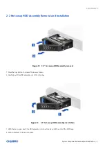
Figure 12
3.5” hot
-swap HDD assembly removal ...................................................................................... 20
Figure 13
3.5” hot
-swap HDD assembly installation ................................................................................. 20
Figure 14
3.5” HDD removal (tool
-less type) ............................................................................................ 21
Figure 15
3.5” HDD installation (tool
-less type) ........................................................................................ 21
Figure 16
3.5” HDD removal (screw type)
................................................................................................ 22
Figure 17
3.5” HDD
installation (screw type) ............................................................................................ 22
Figure 18
2.5” HDD/SSD removal in 3.5” tray (screw type)
....................................................................... 23
Figure 19
2.5” HDD/SSD
installation
in 3.5” tray (screw type)
.................................................................. 23
Figure 20 Removal of whole system from the rack (latch type) ................................................................ 24
Figure 21 Installation of whole system into the rack (latch type) .............................................................. 24
Figure 22 Fan module removal (4056) ...................................................................................................... 25
Figure 23 Fan module disassembly (4056) ................................................................................................ 25
Figure 24 Fan module assembly (4056) .................................................................................................... 26
Figure 25 Fan module installation (4056) ................................................................................................. 26
Figure 26 Air baffle removal .................................................................................................................... 27
Figure 27 Air baffle installation ............................................................................................................... 27
Figure 28 PCIe card blank removal ........................................................................................................... 28
Figure 29 Cards and brackets installation ................................................................................................ 28
Figure 30 CRPS module installation-1 ....................................................................................................... 29
Figure 31 CRPS module installation-2 ....................................................................................................... 29


