background image


17/17 

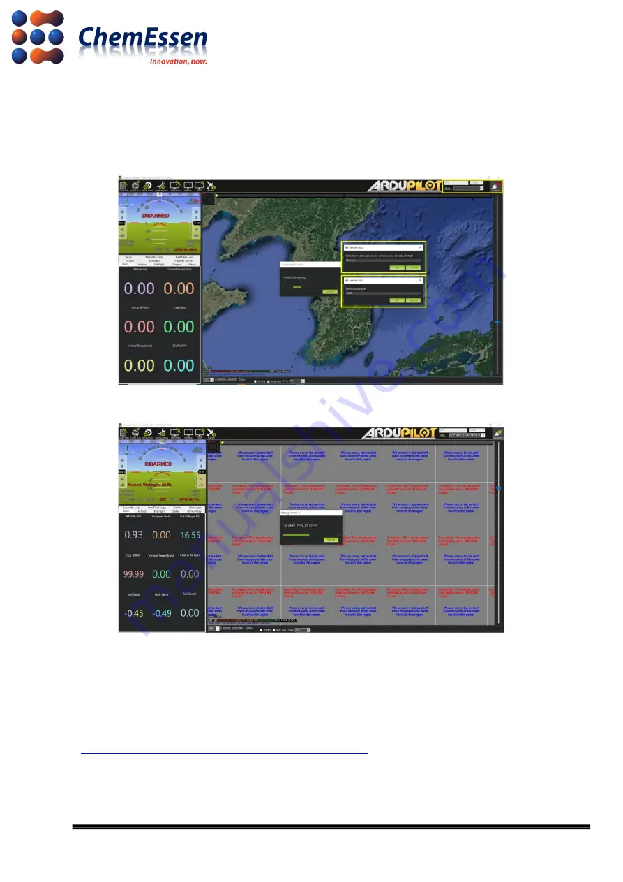
3) Change the communication method of the mission planner to TCP, change the baud rate value 
to 115200, and then click [Connect]. Enter the IP for the drone in the remote host pop-up window, 

and  enter  “14000”  in  the  remote  port  pop

-up  window,  and  try  to  connect.  You  can  check  the 

attempt of wireless communication trying to open the parameters. 


Figure # 16 Mission Planner Connect 

 Remote Host/Port 


Figure # 17 Mission Planner 

 Wireless Communication Check 

 Configure according to the type and specifications of the drone such as frame type, accel 

calibration, compass, etc. After completing the flight test, use the ROPPOR software to fly. 

Configuration provided by ArduPilot 

https://ardupilot.org/copter/docs/configuring-hardware.html


Содержание ROPPOR

Страница 1: ...Configuration Guide v1 0 for ROPPOR Art Drone Connection Chemessen Inc You can watch the video Youtube about this document ...

Страница 2: ...s is only one example of testing the products of various manufacturers and the services of mobile carriers and confirming their integration with our software and the durability of each hardware and mobile communication network It does not guarantee the stability the function for a specific purpose etc The user is solely responsible for the selection interlocking and operation results of all hardwa...

Страница 3: ...CB Antenna u FL Plug 100mm 5 5 Sixfab Raspberry Pi 3G 4G LTE Base HAT 5 1 2 Drone 5 1 Drotek Pixhawk 3 Pro 5 2 Drotek All in One module Pixhawk 3 pro 5 3 Drotek Voltage current 5 3V power supply Mounted 5 4 JST GH to JWT 28AWG 6 pins Silicone cable 5 5 Drotek SIRIUS RTK GNSS ROVER F9P 5 1 3 Recommendations 6 2 Companion Computer LTE Device 7 2 1 Preparation 7 1 Main Power Cable 7 2 2 Connection 8 ...

Страница 4: ...4 17 3 LED Board 12 3 1 Preparation 12 3 2 Connect 13 4 Firmware and Parameter 14 4 1 Firmware Installation 14 4 2 Parameter Change 14 5 Check Wireless Communication and Connection 16 ...

Страница 5: ...uct raspberry pi base hat 3g 4g lte minipcie cards 1 2 Drone 1 Drotek Pixhawk 3 Pro https store drotek com 821 pixhawk pro autopilot html 2 Drotek All in One module Pixhawk 3 pro https store drotek com 819 all in one Pixhawk html 3 Drotek Voltage current 5 3V power supply Mounted https store drotek com 809 voltage current 53v power supply mounted html 4 JST GH to JWT 28AWG 6 pins Silicone cable ht...

Страница 6: ...tions screw tightening cable damage and defective soldering in drone manufacturing Assemble with care The shape of drone and overall hardware composition are user s choice The company introduces the guide for connection with LTE based ROPPOR software a fter taking the shape of a general drone quad copter ...

Страница 7: ... test https sixfab com product category raspberry pi shields 2 1 Preparation 1 Main Power Cable Prepare the main power 5V cable to supply power to the micro USB power of Raspberry Pi This cable is not provided and thus can assemble your own power cable The company has supplied power by connecting 5V 3A UBEC to the PDB 12V of the drone The method of the company does not guarantee drone control for ...

Страница 8: ...please refer to the Smart Device Application Software Installation Document Connect as follows 1 Companion Computer Insert the micro SD card installed with SDAS to Raspberry Pi Figure 2 Raspberry Pi 3A Layout 2 LTE Device Mount the LTE module to the mini PCIe socket of the LTE base hat Then insert the activated USIM into the SIM socket Figure 3 LTE Base Hat EC25 LTE Module Layout ...

Страница 9: ...9 17 Use the long header to connect the Raspberry Pi and the LTE base hat Figure 4 Component Long Header 3 Companion Computer LTE Device Figure 5 Result of Connection ...

Страница 10: ...2 Connect the LTE full band PCB antenna to the MAIN and DIY of the LTE module Figure 6 Connection Result by Device 3 Use the JST GH to JWT 28AWG 6 pins silicone cable to connect to the GND TX and RX of the LTE base hat to Telem1 port of Pixhawk 3 Pro Make sure that the cable connected to the long header is stable Figure 7 LTE Base Hat Pinout ...

Страница 11: ... JWT 28AWG 6 pins Silicone cable Pixhawk 3 Pro Pinout 4 Last connect the main power line to the micro USB power of the Raspberry Pi Figure 9 Final Result The method of the company does not guarantee drone control for the user ...

Страница 12: ...e master Drone_hardware 3D_Printing 3 1 Preparation The LED board in the link above consists of PCB main power line and JWT 3 pin Servo Signal cable Prepare a cable to supply main power to the LED board and a cable to receive LED signal from FC Figure 10 LED Board PCB Cable Composition Example ...

Страница 13: ...e operational with low power and we recommend that you search for and a pply mass produced LED that can maintain the same level of brightness for all drones or to mass produce and apply such LED 3 2 Connect Figure 11 Pixhawk 3 Pro Pinout LED Board Connect Connect the main power cable to supply power to the LED board Then connect the RGB signal cable to the servo rail indicated as R 1 G 2 and B 3 ...

Страница 14: ...ing document for basic firmware installation method https ardupilot org copter docs common loading firmware onto pixhawk html connect autopilot to computer The company has completed the final test with Arducopter V4 0 3 Quad Figure 12 Mission Planner Firmware Installation Screen Use USB to micro USB to connect the PC and FC and then use the Mission Planner to install the suitable firmware for the ...

Страница 15: ...f Telem1 based on Pixhawk 3 Pro SERIAL1_BAUD port to 115200 Input value 115 And then click Write Params to apply and save Figure 14 Mission Planner Configuration Full Parameter List Parameter values suggested by the company is irrelevant to the user s drone control Configure and check the parameters according to user operation and hardware configuration aside from other applicable values before op...

Страница 16: ...ion of SDAS VPN etc Wireless communication is checked as follows 1 Launch ROPPOR to check wireless communication Disconnect the wired connection between the PC and the drone and power the drone with a battery 2 Rebooted drone is displayed on the ROPPOR screen within minutes and you can check the IP for the drone in the Dashboard Figure 15 Check Connection in ROPPOR Dashboard IP ...

Страница 17: ... You can check the attempt of wireless communication trying to open the parameters Figure 16 Mission Planner Connect Remote Host Port Figure 17 Mission Planner Wireless Communication Check Configure according to the type and specifications of the drone such as frame type accel calibration compass etc After completing the flight test use the ROPPOR software to fly Configuration provided by ArduPilo...

Отзывы: