background image

Page 32 

6.7.5.  Span and Zero Coefficients 

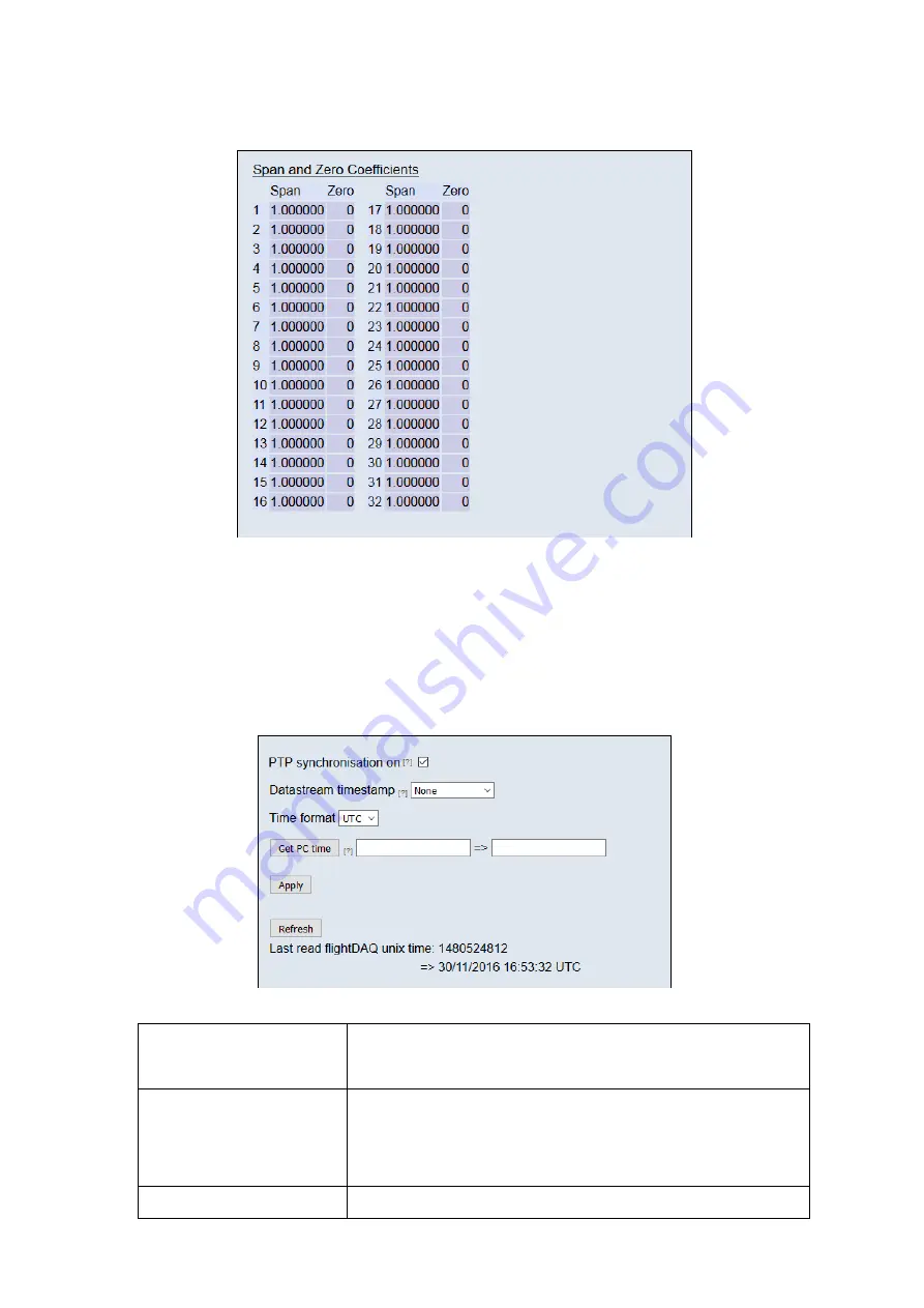
This section displays the Span and Zero coefficients currently stored within the flightDAQ as a result 
of a linear calibration


Figure 5.12, Span and zero coefficients 


6.8. Timestamp 

This page allows the user to edit the timestamp settings of the flightDAQ. This timestamp will allow 
the user to get millisecond level accuracy timestamps on the data packets. If the timestamp is 
enabled it will have an effect on the maximum transmission rate. 
The last read Unix time displays the internal flightDAQ time at the last time it was read, the top of 
the two lines shows the Unix timestamp, and the bottom of the two lines shows the time in a user-
friendly format. 


Figure 5.13, Timestamp 


‘PTP synchronisation on’ 
checkbox 

This allows the user to select whether any timestamps that may be 
added to the data stream are PTP synchronised or not. Please note this 
will only work if there is a PTP grandmaster on the same network as the 
flightDAQ 

‘Datastream timestamp’ 
dropbox 

The user can use this to select where the timestamp is positioned in the 
data stream, either none which will turn the timestamp off, start of cycle 
which will place a timestamp at the beginning of all the channels and 
every channel which will read the timestamp for every channel. It should 
be noted that the latter 2 options will reduce the maximum transmission 
speed data stream. 

‘Time Format’ 

This chooses the time format of the device Timestamping, Either UTC 
(Universal coordinated time) or TAI (Temps Atomique International)  

Содержание flightDAQ-Mk2

Страница 1: ...Road North Walsham Norfolk NR28 0AJ ENGLAND Tel 01692 500555 Fax 01692 500088 flightDAQ Mk2 Pressure Scanner Acquisition System INSTALLATION AND OPERATING MANUAL e mail info chell co uk Visit the Chel...

Страница 2: ...0203 Issue 1 9 ECO 3801 Date 27th November 2020 Chell s policy of continuously updating and improving products means that this manual may contain minor differences in specification components and soft...

Страница 3: ...nner in run mode 15 4 2 Scanner in calibrate or purge mode 15 5 Operation of the instrument 16 5 1 Powering up the flightDAQ 16 5 2 Connecting to the FlightDaq 16 5 2 1 Connecting to the Webserver 16...

Страница 4: ...g 35 9 flightDAQ INT Connector interface adaptor 36 9 1 Case Assembly 36 9 2 Power Connector Mating connector 2 1mm DC power jack 36 9 3 Can Connector Mating connector 9 way D type male 36 9 4 Trigger...

Страница 5: ...lightDaq2 features an SQDC quick disconnect coupling for the measurement lines meaning a wide variety of tubing types can be connected to it Other pneumatic interfaces are also available The flightDAQ...

Страница 6: ...st significant programmable device ID Address 0xn n Next most significant programmable device ID BRP CAN bus timing see Infineon data sheet TSEG1 CAN bus timing see Infineon data sheet TSEG2 CAN bus t...

Страница 7: ...CAN Lo Power supply return is internally bonded to the product case EMC ground may be made via the product mounting flange Hot plugging the power to the flightDAQ at the connector can cause permanent...

Страница 8: ...Page 7 3 Mechanical Specifications 3 1 Product Mechanical Drawing 32 channel SQDC version A 3D CAD model of the product is available from Chell Instruments Ltd on request...

Страница 9: ...Mechanical Overview 73 ZOC Version A 3D CAD model of the product is available from Chell Instruments Ltd on request Measurement Port 73ZOC Power and Communication Connector TVP02ZN Control Purge Air S...

Страница 10: ...Page 9 3 3 Product Mechanical Overview QDCM 64 Channel Version A 3D CAD model of the product is available from Chell Instruments Ltd on request...

Страница 11: ...connector for 0 040 1 0mm i d flexible tubing SQDC R 32 04 Mating connector for 0 063 1 6mm i d flexible tubing SQDC R 32 07 Mating connector for 1mm o d solid tubing SQDC R 32 02 Mating connector fo...

Страница 12: ...n dry gas with a pressure 7 to 8 bar gauge Purge Purge supply pressure Clean dry gas with a pressure 7 bar gauge Care must be taken if the purge pressure exceeds the pressure range of the scanner Cali...

Страница 13: ...Page 12 3 5 Measurement Connector 64 channel Scanivalve 73ZOCFB 040 use gasket 6557 1...

Страница 14: ...Page 13 3 6 Measurement Connector TE QDCM 3601000101 use gasket QDCM 3600000100 Channels 1 32 Connector 1 Channels 33 64 Connector 2...

Страница 15: ...are all connected to the calibrate port and the measurement lines are connected to the purge supply valve Purge gas supplied to the purge port on the top of the flightDAQ2 can then be switched by usi...

Страница 16: ...Page 15 4 1 Scanner in run mode 4 2 Scanner in calibrate or purge mode...

Страница 17: ...If the power supply should move outside of these limits the FlightDaq will sense this and shut itself off until a correct power supply is restored 5 2 Connecting to the FlightDaq One the blue LED is f...

Страница 18: ...ion 900170 X X When using high data rates Windows may require some registry modifications to enable the higher speeds Please refer to section 4 1 4 in the MicroDaq2 and flightDaq2 user programming gui...

Страница 19: ...ading new coefficients and the means to managing calibration data Data from the calibration procedure and resulting coefficients may be loaded stored and exported for filing reuse and examination in o...

Страница 20: ...the scanner to cal purge 2 Wait 1 second 3 Vent C1 valve 4 Wait 0 5 second 5 Acquire 128 pressure values average them together and calculate the zero offsets 6 Actuate C2 valve to move the scanner to...

Страница 21: ...sure is used where there is a possibility to charge a blocked measurement line to this pressure When the scanner is returned to RUN mode the differential transducer would be exposed to this pressure a...

Страница 22: ...pend on the comms protocol selection Protocol option list Selects the format that the data will be transmitted as options are 16 bit LE 16 bit BE for all protocols and eng units as an extra option for...

Страница 23: ...it should be noted that due to an oddity in the protocol firmware when switching protocol from UDP back to TCP the user has to select a data rate as well to complete the switch back to TCP Settings a...

Страница 24: ...lightDAQ uses standard CAN message arbitration id s and the unit is assigned the most significant 2 digits of the Hex base address For the digits 0x1A for example data for the first 4 channels will be...

Страница 25: ...ture values as raw unsigned 16 bit and calibrated engineering units may be displayed Values are updated automatically once a second with the default view being Pressure Eng Use the Select button to st...

Страница 26: ...a non temperature calibration may be performed at a single temperature Figure 5 7 shows the Calibration tab controls which are further explained in table 5 6 The Live values section is an indicator of...

Страница 27: ...mperature calibration Unchecked only temperature point 1 is available to the user and the system will calculate coefficients for a non temperature calibration Live Values The live values of the curren...

Страница 28: ...trol Function Range Shows the floating point value for the range contained within the scanner x3 derange Shows the floating point value for the sensitivity derange constant contained within the scanne...

Страница 29: ...ion controls Figure 5 9 Filtering group Control Function Pressure Input Impulse Filter Check box to apply impulse filter to pre calibration data will remove single impulse noise events in the pressure...

Страница 30: ...1 on start up which details the flightDAQs serial number IP address etc in an ASCII comma separated list should not be used if remote UDP address port has been configured and auto streaming has been s...

Страница 31: ...number of channels on the attached scanner should be chosen from the Channels drop down It is important that this number is correct when performing any calibration or reading data from flightDAQ Full...

Страница 32: ...tput data will be in BAR of PSI Pressure type Chooses whether the data stream values are represented as absolute pressure approx 2psi to scanner full scale 15psi or differential pressure Heater contro...

Страница 33: ...the time in a user friendly format Figure 5 13 Timestamp PTP synchronisation on checkbox This allows the user to select whether any timestamps that may be added to the data stream are PTP synchronise...

Страница 34: ...t the applied pressure either manually or by clicking the defaults button The accept button will store the current values of the line selected by the radio button and move the radio button down to the...

Страница 35: ...on When the hardware trigger is activated the flightDAQ will wait for the first pulse The time that this first pulse is generated can be measured by the user and therefore the time of the first set o...

Страница 36: ...ual basis and Chell Instruments Ltd Provides a fully traceable facility for this purpose 8 3 Adjustment There are no user adjustments in the instrument The user is strictly forbidden from removing the...

Страница 37: ...er Gnd 9 3 Can Connector Mating connector 9 way D type male Pin Number Designation 2 CAN_L 5 Gnd 7 CAN_H 4 N C 5 0V 9 4 Trigger Connector Mating connector 50 Ohm BNC Pin Number Designation Centre TTL...

Отзывы: