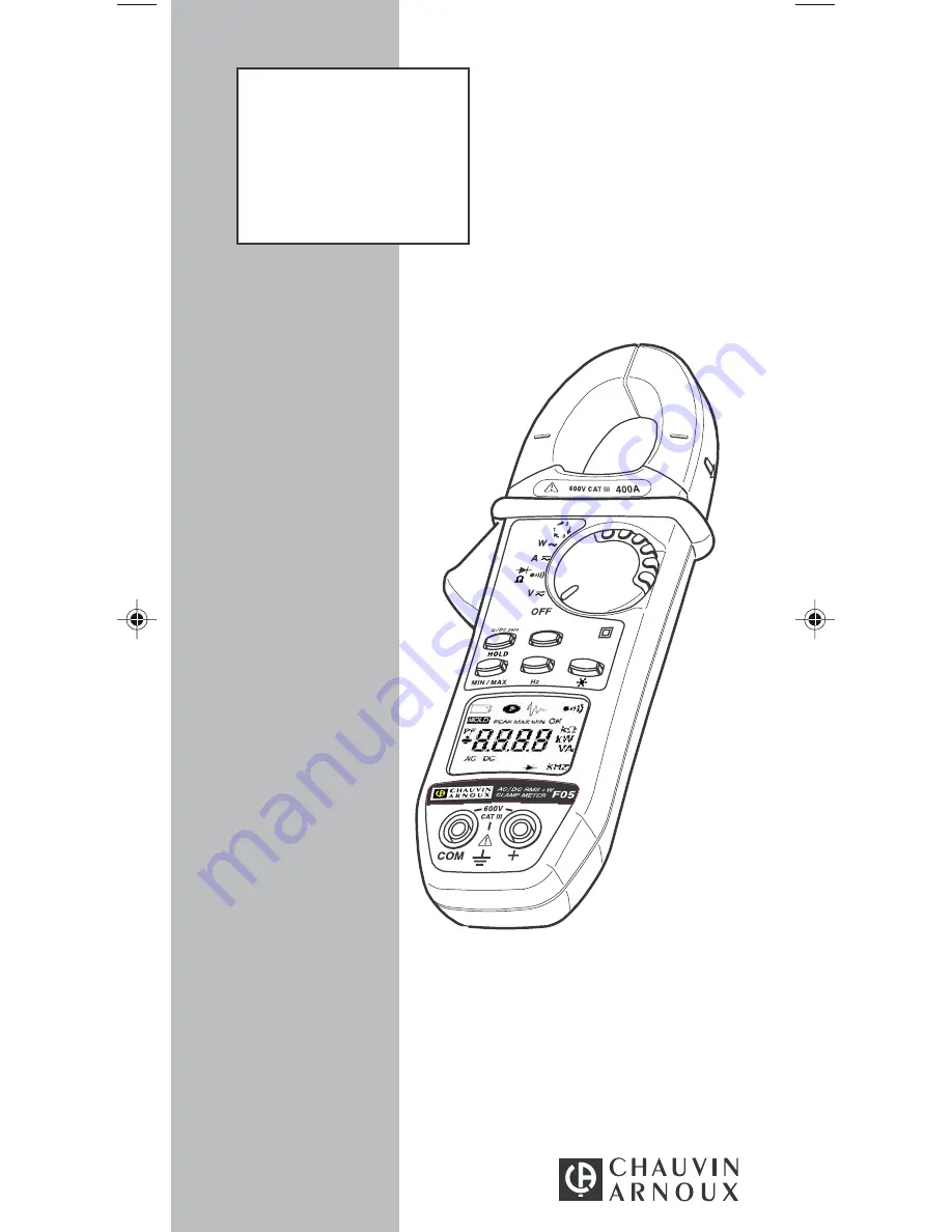
Chauvin Arnox F 05 Скачать руководство пользователя страница 1

Pince multimètre

Clamp multimeter

Vielfachmesszange

Pinza multimetro

Pinza multimétrica

F 05

F R A N Ç A I S

E N G L I S H

D E U T S C H

I T A L I A N O

E S P A N O L

Notice de fonctionnement

User's manual

Bedienungsanleitung

Libretto d’Istruzioni

Manual de Instrucciones

Содержание F 05

Страница 1: ...Vielfachmesszange Pinza multimetro Pinza multim trica F 05 F R A N A I S E N G L I S H D E U T S C H I T A L I A N O E S P A N O L Notice de fonctionnement User s manual Bedienungsanleitung Libretto d...

Страница 2: ...ecautions detailed PRECAUTIONS FOR USE Never use on networks with voltage higher than 600 V in relation to the ground and whose overvoltage category is higher than III i e fixed industrial and domesti...

Страница 3: ...ode 39 3 12 6 Selections possible in continuity function 39 3 12 7 Selection OF INRUSH function 39 3 12 8 3 12 8 Suppression of automatic stop 39 3 12 9 Activation of the V Live function 40 3 12 10 Mo...

Страница 4: ...cable resistance zero Compliance with CEI electrical safety standards and CE markings Lightness and ruggedness for field use With all new additional features Inrush function in particular for measurem...

Страница 5: ...conductor test continuity test Power factor calculation Phase order indication measurement see description 3 11 MIN MAX operates by end around shift on short pressure MIN MAX V and A Functions Other f...

Страница 6: ...display includes the digital display of the measured values the related units and symbols Digital display 4 digits 9999 points 3 decimal points and signs DC and peak measurement OL Positive value rang...

Страница 7: ...high pitched sound prohibited key Short and low sound Quit MIN MAX mode 2 short and high pitched beeps validation of a configuration parameter Short and medium sound every 400 ms voltage measured hig...

Страница 8: ...io indication is activated if the V Live function is selected see 3 12 9 Display range 40 V 400 V 4000 V 1 Measuring range 2 0 2 V to 40 0 V to 400 to 600 V 39 99 V 399 9 V 400 to 900Vpeak Accuracy 1...

Страница 9: ...rom the value of the resistance measured later Note If the value measured is higher than 2 this correction is stopped and the memorised correction value is reset to zero Characteristics Display range...

Страница 10: ...on to be tested The measurement current moves from the terminals to the COM terminal It corresponds to the direct testing of the semi conductor junction Short circuit junction audio indication for a t...

Страница 11: ...1 A 1 In DC the display indicates OLabove 400 A and OL above 400 A 600 A in PEAK mode In AC the display indicates OL over 400 Arms 900 V in PEAK mode 2 In AC if the value of the current measured is 0...

Страница 12: ...frequency 200 ms at 50 Hz Range for use 5 A peak for the first period of the signal 3 8 Power measurement W 1 Connect the measurement leads to the instrument s terminals complying with the polarities...

Страница 13: ...the clamp configured in power measurement switch on position W and correctly connected see 3 8 perform a short press on the yellow key the power factor is displayed The power factor is by definition a...

Страница 14: ...ion of a reference period on one phase L1 L2 for example 2 Integration of a reference period on one phase L1 L3 3 Calculation of the time delay between reference and measurement periods enabling deter...

Страница 15: ...seconds after messages may be displayed leaving L2 after 10 s max MEAS determination of period for measurement in progress contact on L3 a was performed too late more than 10 s after display rEF OK E...

Страница 16: ...key are used to select manually AC measurement DC measurement and return to automatic mode When the mode is selected manually the AC or DC symbol is fixed The selection of this manual mode is impossib...

Страница 17: ...Hold the Yellow key pressed and bring the rotary switch from the OFF position to A position The unit emits a double beep then all the segments of the digital display and the symbol flash The default...

Страница 18: ...ivation by switching from the OFF position of the switch or by actuating any key 4 4 Environmental parameters Temperature Humidity 0 10 20 30 40 50 60 70 80 90 50 40 30 20 10 0 10 20 30 40 50 60 70 80...

Страница 19: ...as per IEC 68 2 6 Auto power OFF per UL94 Housing V0 Jaws V0 Display window V2 4 6 Variations in operating range Quantity Meas range Quantity Influence quantities quantities influenced Typical Maxi Ba...

Страница 20: ...1 ct PF 0 7 and I 5 A 1 R 1 ct inductive and 0 5 and I 10 A W 0 5 R 3 R 1 ct capacitive 0 2 and I 20 A 8 R 1 ct Rejection of serial mode 0 600 V 50 Hz VDC 50 dB 45 dB in DC 0 400 A 50 Hz ADC 40 dB 35...

Страница 21: ...00 6 00 8 00 100 Hz 1000 Hz 10000 Hz Specified limits Frequency Hz Error measurement I f f 10 Hz 25 00 20 00 15 00 10 00 5 00 0 00 5 00 10 00 100 Hz 1000 Hz 10000 Hz Specified limits Frequency Hz Err...

Страница 22: ...0 88 set of 2 alligator clips NF EN 61010 P01 1018 48 set of 2 cables with IP2X touch prods P01 2951 57 carrying case N 7 P01 2985 32 Different measurement accessories widen the scope or provide new f...

Страница 23: ...er 7 2 Storage If the clamp is not used for a period of more than 60 days remove the battery and store it separately 7 3 Cleaning The clamp must be disconnected from any external electrical source and...

Отзывы: