background image


Connecting (Cabling) Each MVP™ 


MVP™ (12/18/37.5) Series Getting Started User Manual, Rev. 10  

-13- 

Connecting the 

Signal Input 


The MVP™  video wall system you design can use  two  basic  setup configurations  to 
connect the signal to the video wall: (1) a configuration using 24 or less panels, and (2) a 
configuration  using more than 24 panels. Refer to the following  diagrams.  See  the 
following section for connecting power to the MVP™  system, and connecting power and 
signal between joined panels. 


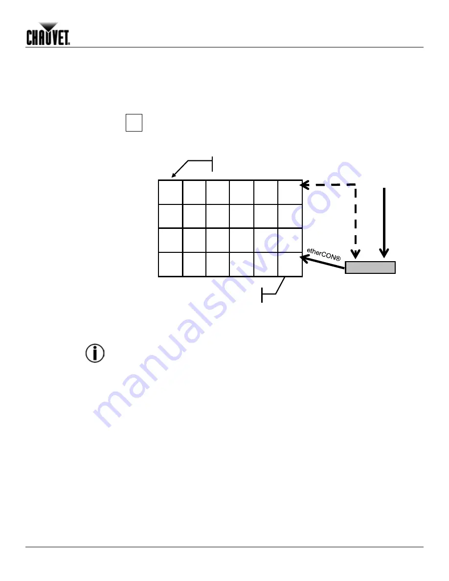
The following configuration of 24 panels shows a direct connection from the 
signal to the MVP™ Driver into the first panel’s Signal Input socket. Refer to the 

MVP™ Driver Quick Reference User Manual

 for information and instructions 

on the MVP™ Driver. 


The MVP™ system maximum signal load is 24 or less panels on a single signal 
cable connection.

 When using more than 24 panels in a video wall design, you will need 

a MVP™ Signal Distributor and additional signal cables to accommodate the number of 
panels over 24. An MVP™ Signal Distributor output supports up to 8 signal output lines, 
providing up to 192 total panels that can be connected from the MVP™ Signal Distributor. 
You also can add more MVP™ Signal Distributors to a MVP™ video wall system. Refer to 
the 

MVP™ Signal Distributor Quick Reference Guide 

for more information. 


Single MVP™ (panel) 

Signal Input socket 

MVP™ Driver 

DVI-D 

Backup 

Connection 

Содержание MVP 12

Страница 1: ...Getting Started User Manual 12 Series 18 37 5 ...

Страница 2: ...print this manual for professional information purposes only CHAUVET expressly prohibits the usage copy storage distribution modification or printing of this manual or its content for any other purpose without its written consent Document Printing For best results print this document in color on letter size paper 8 5 x 11 inches double sided If using A4 paper 210 x 297 mm configure your printer to...

Страница 3: ...5 4 Product Dimensions 6 MVP Pixels Per Panel 6 3 Setup 7 AC Power 7 AC Plug 7 Power Linking 7 4 Mounting 8 Orientation 8 Truss Installation 8 5 Joining Each MVP Creating a Modular Design 9 Vertically Joining the Panels 9 Horizontally Joining Panels 11 6 Connecting Cabling Each MVP 12 Testing Signal and Power Connections 12 Using the MVP Test Button 12 Connecting the Signal Input 13 Connecting Pow...

Страница 4: ...tarted User Manual Rev 10 8 Operation 19 Additional Hardware and Software 19 About LED Studio 20 Description 20 9 Technical Information 21 MVP Maintenance 21 Troubleshooting User Manual 21 Returns Procedure 22 Contact Us 22 10 Technical Specifications 23 ...

Страница 5: ...g material for inspection For other issues such as missing components or parts damage not related to shipping or concealed damage file a claim with CHAUVET within seven 7 days of receiving the merchandise Typographic Conventions Convention Meaning 1 512 A range of values in the text 50 60 A set of mutually exclusive values in the text Italics A reference to a section chapter or external document S...

Страница 6: ...ed to the proper voltage provided in this manual s specifications and or the specification sticker on the product Never try to repair the product Repairs carried out by unskilled people can lead to damage or malfunction Please contact CHAUVET Technical Support Any damages caused by manual modifications are not subject to warranty CHAUVET will not accept liability for any resulting damages caused b...

Страница 7: ...tudio software available as download from the Internet Refer to the LED Studio User Manual for detailed information and instructions on using LED Studio Features Packaged in a convenient CHAUVET flight case that includes either two 2 or six 6 MVP panels Lightweight modular system Provides multiple graphics based on which MVP is used and how the video wall is assembled Uses Neutrik powerCON and Neu...

Страница 8: ...0 Product Overview MVP 12 MVP 18 and MVP 37 5 Signal Input Power Input Signal Output Power Output Vertical rigging Rigging Plate Rigging Plate Rigging Plate Rigging Plate LED Strip Horizontal locking knob Fast Lock Fast Lock Handle Vertical rigging Underside of MVP Panel Ledge ...

Страница 9: ...al Rev 10 5 The difference between each MVP model is the pixel pitch space between the LED strips and the number of pixels LEDs on each strip The basic housing and components are identical Refer to the previous MVP 37 5 illustration MVP 18 MVP 12 MVP 37 5 ...

Страница 10: ...refer to the Technical Specifications table at the end of this User Manual MVP 12 MVP 18 MVP 37 5 Pixels per Panel 48 x 48 32 X 32 16 X 16 Total Pixels 2 304 1 024 256 You will use the number of pixels per panel and the screen resolution you would like to use for your video wall display to calculate the number of panels horizontally and vertically supported by a single MVP Driver This Driver is re...

Страница 11: ...er connect this product to a rheostat variable resistor or dimmer circuit even if the rheostat or dimmer channel serves only as a 0 to 100 switch AC Plug Each MVP comes with a power linking cord to connect power between panels however the power input cord is not included The power input cord must be purchased separately CHAUVET recommends the Neutrik powerCON extension cable item number PCEXT50FT ...

Страница 12: ...uration and maintenance CHAUVET recommends following the general guidelines below When selecting an installation location consider ease of access for operation and routine maintenance Make sure to hang away from any flammable material as indicated in the Safety Notes section Never mount in places where rain extreme temperature changes or restricted ventilation may affect it Make sure that the stru...

Страница 13: ...erchangeable you can create a video wall by joining several of the same model or joining different models to create a larger or more complex video wall Vertically Joining the Panels Each MVP can be easily joined vertically using the two 2 fast locks located at the top corner of each panel and the vertical rigging located on the bottom of the panel at each corner These connectors can be recessed if...

Страница 14: ...e diagram 1 When connecting two 2 panels pull out the vertical rigging latch making sure it is pushed outward 2 The fast locks on the lower panel should be pointing up 3 Align the top and bottom panels exactly on top of each other Push the vertical rigging inward to fasten Once the panels are fastened make sure you turn the vertical rigging latch toward the center of the panel to lock the panels i...

Страница 15: ... the two horizontal locking knobs on the inside left hand top and bottom of each panel Instructions 1 Align each knob with the corresponding hole on the right hand outside of the panel to which you are joining 2 Once aligned push in and twist clockwise a quarter turn to lock the two panels horizontally together 3 You will feel the two panels lock together Horizontal locking knob ...

Страница 16: ... should be blinking rapidly to indicate good reception Using the MVP Test Button Each MVP also has a Test button used to ensure all LED strips in each panel are functional Use the Test Button on each panel to perform a self test If self testing you must perform the test individually for each MVP You do not need to connect to a signal or use software When using the Test button make sure the MVP is ...

Страница 17: ...the first panel s Signal Input socket Refer to the MVP Driver Quick Reference User Manual for information and instructions on the MVP Driver The MVP system maximum signal load is 24 or less panels on a single signal cable connection When using more than 24 panels in a video wall design you will need a MVP Signal Distributor and additional signal cables to accommodate the number of panels over 24 A...

Страница 18: ...ic configuration to connect the signal from one panel to the next is as follows The source signal is connected to the first panel s Signal Input or Output A signal cable is then connected to the first panel s Signal Output and connected to the next panel s Signal Input The connections continue until all panels are connected The direction of the cables used to make the signal connections can vary T...

Страница 19: ...ver MVP Driver connection to the MVP Signal Distributor Signal cable connections as determined by the number of panels in the video wall design Every group of 24 panels will require another signal cable from the MVP Signal Distributor Eight 8 signal cables can be connected to a single MVP Signal Distributor MVP Driver DVI D MVP Signal Distributor Up to 24 Panels etherCON Up to 24 Panels etherCON S...

Страница 20: ...d to make the power connections can vary The power input cord for the main must be purchased separately CHAUVET recommends the Neutrik powerCON extension cable item number PCLEAD50FT available from CHAUVET Connect power between the panels using the same procedure as the signal only using the Power Input and Power Output connectors You must adhere to the power linking specifications for each MVP mo...

Страница 21: ...nel are working optional Step 3 Create a stable mounting surface i e truss or other stable surface for MVP mounting Step 4 Mount the first top row of the MVPs Refer to the Mounting section in this User Manual Step 5 Based on your video wall configuration design join each panel either horizontally or vertically using the instructions in the section Joining Each MVP Step 6 Connect the signal source ...

Страница 22: ... single PC Refer to the MVP 526P Signal Processor Quick Reference Guide and the MVP Signal Distributor Quick Reference Guide for information on those video wall components MVP Media System Flexibility In this illustration the top driver provides playback of pre recorded content to the first series of panels and the second driver receives video from external sources allowing for playback of live co...

Страница 23: ...needed to mount MVPs Rigging Kit Rigging Kit single Rigging Kit dual 12090352 12090355 12090356 MVP RK MVP RK1 MVP RK2 Neutrik etherCON Signal Extension optional MVP Signal Extension 18 in MVP Signal Extension 5 ft MVP Signal Extension 10 ft 19090363 19090364 19090365 MVPU SIG18IN MVPU SIG5FT MVPU SIG10FT Neutrik powerCON Extension optional powerCON Extension 18 in powerCON Extension 5 ft powerCON...

Страница 24: ... LED Studio enables you to create and control your MVP Video Wall display by addressing the panels included in your video wall and specifying and controlling video wall design Once you have physically created your modular video wall design by joining the panels connecting power signals and the MVP Media System you recreate that design within LED Studio You then upload specific audio video text and...

Страница 25: ...tions are thoroughly dry before reconnecting power and signal cables Always dry the external surfaces carefully after cleaning them Troubleshooting Guide Symptom Cause s Action s All LEDs are blinking Contact failure Fix the loose LEDs or try re plugging LEDs on a specific circuit are not lit working Power output cable may be connected incorrectly Remove and connect correctly Power cables may be p...

Страница 26: ... the box Your name Your address Your phone number The RMA number A brief description of the problem s Be sure to pack the product properly Any shipping damage resulting from inadequate packaging will be the customer s responsibility Proper FedEx packing or double boxing are recommended packaging methods CHAUVET reserves the right to use its own discretion to repair or replace returned product s Co...

Страница 27: ...0 VAC 50 60 Hz 100 240 VAC 50 60 Hz Voltage Selection Auto ranging Auto ranging Auto ranging Power Consumption 120 V 60 Hz 127 W 1 1 A 120 W 1 06 A 72 W 0 6 A Power Consumption 208 V 60 Hz 139 W 0 68 A 139 W 0 68 A 78 W 0 39 A Power Consumption 230 V 50 Hz 144 W 0 63 A 144 W 0 67 A 80 W 0 36 A Power Linking 120 V 60 Hz 7 units 7 units 13 units Power Linking 208 V 60 Hz 11 units 11 units 20 units P...

Страница 28: ...CHAUVET 5200 NW 108 th Avenue Sunrise FL 33351 USA 800 762 1084 954 929 1115 FAX 954 929 5560 www chauvetlighting com MVP 12 18 37 5 Series Getting Started User Manual Rev 10 February 2012 ...

Отзывы: