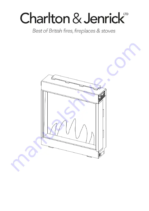
LED Electric Fire
Model: Polaris 620
INSTALLATION AND OPERATION INSTRUCTIONS
Please read the instructions carefully before installation or
use and keep for future reference
Страница 1: ...LED Electric Fire Model Polaris 620 INSTALLATION AND OPERATION INSTRUCTIONS Please read the instructions carefully before installation or use and keep for future reference ...
Страница 2: ...ty Information 2 2 Technical Specifications 3 3 Parts and Hardware 4 4 Appliance Dimensions 6 5 Installation Instructions 6 6 Operating Instructions 15 6a Manual Control Panel 16 6b Remote Controls 17 7 Maintenance 23 8 Others 24 ...
Страница 3: ... power cord is damaged it must be repaired by the manufacturer its authorised service centre or professional person 1 9 Warning in order to avoid overheating do not allow the appliance to be covered or let the air inlet outlet become obstructed Please note the warning on the appliance 1 10 To reduce the risk of fire keep textiles curtains or any other flammable material a minimum distance of 1 met...
Страница 4: ...0 Supply Voltage AC 230 240V 50Hz Maximum power consumption 1800 2000W Power for flame effect 30W Max power for mood light 30W Heat Output Nominal heat output Pnom 2000W Minimum heat output indicative Pmin 1000W Maximum continuous heat output Pmax 2000W Auxiliary Electricity Consumption At nominal heat output elmax 12 5W At minimum heat output elmin 12W In standby mode elSB 0 8W Type of heat outpu...
Страница 5: ...liance is intact with no signs of damage caused by transport and no part has been exposed to water If in doubt do not use the appliance and contact an authorised service centre 3 2 Keep plastic wrapping away from children 3 3 Save the original packaging as this may be required in the event of service complaint with product 3 4 Check that all parts are removed from the packing A B C ST 4 8 Flat tai...
Страница 6: ...5 G H I Black Glasses 1 set Vermiculate 1 set Logs 1 set J K L Instruction Manual 1 pc AAA Battery 2 pcs Remote 1 pc M N Power Cord 1 pc Simplified Instruction 1 pc ...
Страница 7: ...ic fireplace may be installed virtually anywhere in your home However when choosing a location ensure that the general instructions are followed 5 1 For best results install out of direct sunlight 5 2 If installing in an existing fireplace and chimney always block the chimney with fibreglass insulation or similar to prevent it sucking air away through Unit mm ...
Страница 8: ...They are as follows Single front aspect This is where the appliance is installed so that only the front window is visible Duel aspect this is where the appliance is installed so that the front and one of the side windows are visible Triple aspect this is where the appliance is installed so that the front and both side windows are visible 5 4 When you unpack the appliance you will note the angle tr...
Страница 9: ... very important that the plug is fully located in the socket and the plastic retention clip that is provided is fitted and securely with the 1 screw provided We further recommend that the power is turned on and the appliance is operated to check function and prove the power connection is sound ...
Страница 10: ...d light instructions 5 6b Refit plate with two ST4 10 screws and connect the mood light strip various lengths available max length 6 metres Note Compatible mood lights are available from Charlton Jenrick Ltd and other makes may not be suitable and will void warranty 5 6c When mood lights are fitted they should be checked for operation before the access is closed off by the installation 5 7 Install...
Страница 11: ...a framework 5 7a1 Prepare the framework as picture Similar if mood lights are fitted they should be checked for operation before the access is closed off by the installation 5 7a2 Fit top vent cover so that it projects 10mm from rear of appliance NOTE Consideration must be given to ensure that air can entre the vents on the underside of the appliance and the top of the appliance The appliance is f...
Страница 12: ...nce into the framework and secure it using fold out the brackets on the top and lower edge of this appliance 5 7a4 Cover the framework by panels or plaster board it can be used directly against the sides and front of the appliance ...
Страница 13: ...12 5 7b Installation of hanging on the wall UNIT mm ...
Страница 14: ...ance on the wall bracket 5 7b10 Check the appliance front face is vertical parallel to the wall 5 7b11 If it not pull the lower edge from the wall until verbal and note the distance from the rear to the wall at the base of appliance 5 7b12 Remove the appliance from the wall bracket and place upside down on the floor 5 7b13 Fix the 2 pcs of the lower wall spacers with the screws provided selecting ...
Страница 15: ...le reflection of these LED s can be seen on the back panel randomly place the remaining glass ember componets over the fuel bed area 5 8e Now open the bag of vermiculite and sprinkle between the embers covering the remaining visible secions of the fuel bed area 5 8f Finally take your time and position the logs and bark pieces provided over the embers create the arranment to your own taste all the ...
Страница 16: ...s running Use the functions on the remote to turn the fire off and ensure the mains switch has been moved to the off position before disconnecting PREPARATION BEFORE USE 6 1 The appliance can be operated by both remote control and the manual controls on the appliance NOTE To use both remote and manual functions the manual on off switch must be in ON position In order to prevent the product becomin...
Страница 17: ...tton to select the colour of flame 3 kinds or return to the OFF position 6a 4 Press FUEL BED button to select the colour of fuel bed 13 kinds or return to the OFF position 6a 5 Press SPEED button to select the speed of flame 5 kinds NOTE The controls on appliance will lose the memory for all function settings when the switch is set to the Off Position When the remote runs out of power or when you ...
Страница 18: ...g The communication frequency between the fire and remote has already been set up If you cannot use the remote with the fire please follow instructions Step 6b37 to initiate this connection in point Standby for Remote Handset 6b 1 The screen shown to the right is when the remote handset is in standby condition Turn on off 6b 2 Press to turn on the flame effect turn off flame effect and heater when...
Страница 19: ...r cycle mode 6b 9 Press the and button to to select the 5 brightness of fuel bed and OFF settings Mood Light Note If mood lights are not connected please ensure the brightness is set to zero 6b 10 Press to enter the mood light adjustment screen 6b 11 Press the and button to cycle through the 13 colours of mood light or a colour cycle mode 6b 12 Press the and button to to select the 5 brightness of...
Страница 20: ...y for normal mode It allows the appliance to go into standby after a set period of time 6b 16 Press to cycle through the settings from Off and 0 5 hours to 9 hours The timer logo and time will show on the screen The heater must be in ON position The heater can be automatically run by using daily timer and weekly timer on the remote Set up Day Time and Comfortable temperature 6b 17 Press to turn on...
Страница 21: ...for 3 seconds or wait for 10 seconds to save and exit the heating time period setting 6b 23 Adjusting the set temperature Press the or button to increase or decrease the temperature on the basis of your comfortable temperature setting ECO means 2 lower than your comfortable temperature setting ECO means 4 lower COMF means 2 higher COMF means 4 higher 6b 24 To check your daily timer settings press ...
Страница 22: ...period setting area Press or to choose hour or minute press or to set the number Max 3 heating periods for a day Minute will increase decrease by 15 minutes per press Press the to set the heating time for the selected day s and return to the week line Hold for 3s or wait for 10s to save and exit the heating time period setting 6b 29 Press and to check your week Timer settings 6b 30 If heating need...
Страница 23: ...e 6b 37 The below operations should be carried out before programming when changing to a new remote or in the event the appliance cannot be controlled by the remote Hold the reset button on the appliance for 3 seconds pen Point may needed until you hear 3 short beeps from the unit release the button Press the button on the remote the programming is finished when you hear 1 long beep from the appli...
Страница 24: ...nit should be disconnected from the power supply until it is cool off Remote Handset Battery Replacement 7 1 When the batteries are at full power the battery symbol will show 7 2 When the batteries are half full the battery symbol will show 7 3 When the batteries are out of power and need replacing immediately the battery symbol will show 7 4 Battery replacement is recommended after 1 year The bat...
Страница 25: ...ailer to take back the old appliance for disposals at least free of charge This fire complies with the Safety Standards EN 60335 1 and EN 60335 2 30 which covers the essential requirements of the Low Voltage Directive 2014 35 EU and the EMC standards EN 55014 1 EN 55014 2 EN 61000 3 2 and EN 61000 3 3 which covers the essential requirements of the European Electro Magnetic Compatibility 2014 30 EU...
Страница 26: ...25 Charlton Jenrick Ltd Unit D Stafford Park 2 Telford Shropshire TF3 3AR Tel 0845 5195 991 Fax 0845 5195 992 www charltonandjenrick co uk ...