


REV 71531-20140505
24
71531
ENGLISH
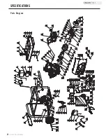
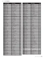
# Part Number
Description
Qty
1
21.061300.00
Recoil Handle
1
2
1.5789.0608
Flange Bolt M6×8
3
3
46.061100.00.2
Recoil Starter Cover, Black
1
4
45.060005.00
Recoil Starter Spring
1
5
45.061102.00
Recoil Starter Reel
1
6
2.10.003
Rope (Ø5×1550)
1
7
45.060003.00
Spring, Ratchet
2
8
45.060002.00
Starter Ratchet (Iron)
2
9
45.060009.00
Spring, Ratchet Guide
1
10
45.060007.00
Ratchet Guide
1
11
45.060008.00
Screw, Ratchet Guide
1
12
1.5789.0612
Flange Bolt M6×12
12
13
2.05.009
Clamp (12.5×7)
2
14
47.080100.01.48
Fan Cover, Yellow
1
15
2.02.007
Nut (M16×1.5)
1
16
1.5789.0629
Flange Bolt M6×29
4
17
45.060001.00
Pulley, Starter
1
18
46.123000.03
Ignition Coil
1
19
47.080001.00
Cooling Fan
1
20 46.120100.05
Flywheel (Electric Start EPA)
1
21
46.091000.03
Air Cleaner Assembly
1
22 46.061000.00
Recoil Assembly
1
23 2.11.007
Oil Seal (Ø35×Ø52×8)
2
24 2.05.050
Wire Clip, 100 mm
1
25 45.030032.00
Sheath, Wire
1
26
2.03.023
Washer (Ø12.5×Ø20×2)
2
27
47.030100.01
Crankcase
1
28 45.127000.02
Oil Level Sensor
1
29 1.5789.0615
Flange Bolt M6×15
2
30 1.276.6202
Bearing 6202
2
31
47.050006.00
Weight Balancer
1
32
47.050100.01
Crankshaft
1
33 46.030008.00
Gasket, Crankcase Cover
1
34 2.04.001
Dowel Pin (Ø9×14)
2
35
46.080600.00
Air Guide, Right Side
1
36 1.276.6207
Bearing 6207
1
37
46.031000.01.48
Oil Dipstick Assembly, Yellow
1
38 45.030007.00
Cover, Crankcase
1
39
1.5789.0840.0.8
Flange Bolt M8×40
7
40 2.03.021.1
Washer (Ø6.4×Ø13×1), Black
1
41
45.110013.00
Shaft, Governor Gear
1
42 45.110100.00
Gear, Governor
1
43 21.110011.00
Clip, Governor Gear
1
44 45.110012.00
Bushing, Governor Gear
1
45 47.050200.00
Connecting Rod
1
46 47.050005.01
Piston
1
47
2.09.004
Circlip (Ø21×Ø1)
2
48 45.050003.00
Wrist Pin
1
49
46.050303.02
Ring, Oil
1
50 46.050302.02
Ring, Second Piston
1
51
46.050301.02
Ring, First Piston
1
52
2.04.004
Dowel Pin (Ø12×20)
2
53 46.030009.02
Gasket, Cylinder Head
1
54 46.080400.00
Air Guide, Lower
1
55 47.010100.01
Cylinder Head
1
56 2.01.010
Stud Bolt (M8×35)
2
57
2.15.002(F6RTC)
Spark Plug (F6RTC)
1
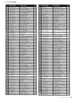
# Part Number
Description
Qty
58 2.08.014
Flange Bolt M10×80
4
59
46.020002.00
Gasket, Cylinder Head Cover
1
60 47.021000.00
Cylinder Head Cover (CPE)
1
61
45.020001.02
Breather Tube
1
62 47.020100.00
Bolt, Cylinder Head Cover
1
63 2.08.039
Bolt, Drain (M12×1.5×15)
2
64 47.041000.01
Camshaft (EPA)
1
65 47.040004.00
Lifter, Valve
2
66 47.040002.00
Valve, Intake
1
67
47.040006.00
Valve, Exhaust
1
68 46.040005.00
Push Rod
2
69
45.040015.00
Retainer, Valve Spring (Down)
2
70
45.040017.00
Oil Seal, Valve
2
71
45.040003.00
Spring, Valve
2
72
23.040010.00
Bolt, Rocker Arm
2
73 45.040001.00
Retainer, Intake Valve Spring
(Up)
1
74
45.040007.00
Retainer, Exhaust Valve Spring
(Up)
1
75
45.040008.00
Rotator, Exhaust Valve
1
76
46.040004.00
Guide Plate, Push Rod
1
77 46.040016.00
Shaft, Rocker Arm
1
78
46.040201.00
Retainer, Rocker Arm
1
79 46.040009.00
Rocker Arm, Intake Valve
1
80 46.040018.00
Rocker Arm, Exhaust Valve
1
81
1.97.1.06
Washer Ø6
2
82 22.040012.00
Screw, Valve Adjustment
2
83 1.6177.1.06
Flange Lock Nut M6
2
84 21.040021.00
Nut, Lock (M6×0.5)
2
85 2.01.008
Stud Bolt (M6×M8×105)
2
86 46.130002.20
Gasket, Insulator (No Asbestos)
1
87 45.130001.00
Insulator, Carburetor
1
88 46.130003.20
Gasket, Carburetor
1
89 47.131000.25
Carburetor
1
90 46.130004.20
Gasket, Air Cleaner
1
91
1.6177.06
Flange Nut M6
3
92
46.091100.03
Base, Air Cleaner
1
93
45.091002.20
Seal, Air Cleaner
1
94 45.091001.20
Separator, Air Cleaner
1
95
45.091003.20
Element, Air Cleaner
1
96 46.091200.04
Cover, Air Cleaner
1
97
1.5789.0835
Flange Bolt M8×35
2
98 45.125100.00
Starter Motor Assembly
1
99 45.125200.03
Relay, Starter (three gear)
1
100 1.93.05
Spring Washer Ø5
2
101 1.16674.0516
Flange Bolt M5×16
2
102 45.110001.00
Shaft, Governor Arm
1
103 2.03.019
Washer (Ø8.2×Ø17×0.8)
1
104 2.11.006
Oil Seal (Ø7×Ø14×5)
1
105 45.110008.00
Pin, Shaft
1
106 45.110003.00
Arm, Governor
1
107 2.08.040
Bolt, Governor Arm (M6×21)
1
108 45.110006.00
Rod Governor
1
109 45.110005.00
Spring, Throttle Return
1
110 45.110007.00
Spring, Governor
1
111 46.080300.20
Air Guide, Upper
1
112
47.131017.21
Standard Main Jet
1
47.131017.21.01
Altitude Main Jet
/


