background image

CHA F-LOOP 2.0 

Page 9 


6.


Connect  one  end  of  the  Flexible  Radiator  Loop 
(b) to the left Radiator Loop Connection (f). 

7.


Connect  the  other  end  of  the  Flexible  Radiator 
Loop to the right Radiator Loop Connection. 

8.


Secure  the  top  middle  of  the  Flexible  Radiator 
Loop  to  the  top  middle  of  the  Coupling  Loop 
with one of the attached Sticky Straps. 

9.


Shape the Flexible  Radiator Loop into a  circular 
shape.  The Coupling Loop and Flexible Radiator 
Loop should be in the same plane. 

10.


Place the CHA F-LOOP 2.0 on a flat surface, such 
as  a  table  top,  or  attach  the  Aluminum  Base 
Plate  (n)  to  a  tripod  or  other  compatible 
antenna mount. 

11.


Connect  the  Coaxial  Cable  Feedline  (m)  to  the 
Loop Connection (l).  

12.


Secure the Coaxial Cable Feedline along the 
Telescoping Mast to ensure easy tuning and 
consistent low SWR. 

13.


Perform  an  operational  test  (see  procedure 
below). 

 
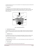
Double Flexible Loop Assembly 

The CHA F-LOOP 2.0 Double Flexible Loop configuration allows you to use the CHA F-LOOP 2.0 on the 80 meter 
ham band by extending the lower frequency of the CHA F-LOOP 2.0 down to 2.8 MHz.  See Plate (4) and perform 
the following steps. 


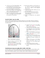
Plate 4.  Double Flexible Loop Antenna. 


1.


Perform  assembly  of  the  Standard  Single 
Flexible Loop configuration. 

2.


Disconnect one end of the Flexible Radiator 
Loop (b) 

“Loop 1”

 from one of the  Flexible 

Radiator Loop Connections (f). 

3.


Connect  the  free  end  of  the  Flexible 
Radiator  Loop 

“Loop  1”

  to  the  Loop 

Extension Barrel Connector (r). 

4.


Connect  one  end  of  the  Flexible  Radiator 
Loop  Extension  (d) 

“Loop  2”

  to  the  open 

Flexible  Radiator  Loop  Connection  from 
step 2. 

5.


Form  the  Flexible  Radiator  Loop  Extension 

“Loop  2”

  into  a  loop,  like  the  Flexible 

Radiator Loop 

“Loop 1”

6.


Attach the top of the Flexible Radiator Loop 
Extension 

“Loop  2”

  to  the  top  of  the 

Coupling  Loop  (c)  using  the  attached  sticky 
strap. 

7.


Connect  the  free  end  of  the  Flexible 
Radiator  Loop  Extension 

“Loop  2”


to  the 

open  end  of  the  Loop  Extension  Barrel 
Connector. 

8.


Set Band Switch (i) to the “A” position.


9.


Perform an operational test (see procedure 
below). 

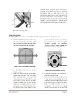
Flexible Booster Loop Assembly (CHA F-LOOP 2.0 TOTAL) 

The CHA F-LOOP 2.0 TOTAL uses the Flexible Booster Loop and a larger Coupling Loop to increase efficiency in the 
60 to 15 meter ham bands.  The CHA F-LOOP 2.0 TOTAL antenna should be installed near the radio set; either 
indoors or in a sheltered outside area, such as a balcony or porch.  Because the magnetic component of an 

Содержание CHA F-LOOP 2.0

Страница 1: ...HF Portable Loop Antenna 2 0 CHA F LOOP 2 0 and CHA F LOOP 2 0 TOTAL Operator s Manual Nevada USA WWW CHAMELEONANTENNA COM VERSATILE DEPENDABLE STEALTH BUILT TO LAST...

Страница 2: ...t voltages that kill Never trust insulation to protect you Stay away from all power lines WARNING Never operate this antenna where people could be subjected to high levels of RF exposure especially ab...

Страница 3: ...receive than an outside full size quarter wave vertical antenna Remarkable for an antenna that is only less than three foot in diameter and covers 3 5 MHz to 29 7 MHz 80 10 meter ham bands The magnet...

Страница 4: ...the primary method of HF radio wave propagation HF radio waves on a frequency below the critical frequency found by an ionosonde are reflected off one of the layers of the ionosphere and back to Eart...

Страница 5: ...t and 4 8 MHz during the day A magnetic loop antenna radiates at all angles from horizon to zenith making it an equally effective antenna for both local and long distance DX communication While not sp...

Страница 6: ...exible Radiator Loop Extension The Flexible Radiator Loop Extension consists of a 102 inch length of shorted coaxial cable with UHF Plugs at both ends The Flexible Radiator Loop Extension enables the...

Страница 7: ...ry Table 2 CHA F LOOP 2 0 and CHA F LOOP TOTAL Frequency Ranges j Coupling Loop Attachment The Coupling Loop Attachment is used to attach the Coupling Loop c to the top of the Telescoping Mast g k Cou...

Страница 8: ...istune the antenna Perform the following steps to assemble the Standard Flexible Loop Antenna see plates 2 and 3 1 Select a location to setup the CHA F LOOP 2 0 antenna The location can be indoors or...

Страница 9: ...e following steps Plate 4 Double Flexible Loop Antenna 1 Perform assembly of the Standard Single Flexible Loop configuration 2 Disconnect one end of the Flexible Radiator Loop b Loop 1 from one of the...

Страница 10: ...when tightening 4 Attach the large 8 inch Coupling Loop c to the Coupling Loop Attachment j located at the top of the Telescoping Mast by placing the threaded hole in the Coupling Loop bracket over t...

Страница 11: ...to the desired frequency range 3 Adjust the Tuning Knob h for maximum receive signal strength Turn the Tuning Knob counterclockwise to decrease the resonant frequency see Plate 8 You will know when yo...

Страница 12: ...r Loop Connections f are securely tightened 3 Inspect Flexible Radiator Loop b for damage Replace if damaged 4 Ensure the Coaxial Cable Connection m is securely tightened to the Loop Connection l 5 In...

Страница 13: ...h may vary Table 3 2 1 SWR Bandwidth Weight 4 lbs Personnel Requirements and Setup Time one operator around 2 minutes Do not use an antenna tuner or coupler with this antenna Accessories The following...

Страница 14: ...Portable Antenna Pioneer References 1 Silver H Ward editor 2013 2014 ARRL Handbook for Radio Communications 91st Edition American Radio Relay League Newington CT 2 1987 Tactical Single Channel Radio...

Отзывы: