


2
1
RED WHT
Figure 4
REMOVE COVER
18
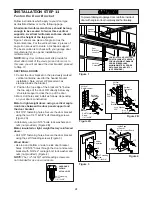
INSTALLATION STEP 6
Install the Door Control
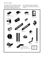
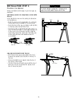
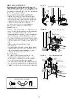
Locate door control within sight of the door at a
minimum height of 5 feet where small children
cannot reach, and away from moving parts of the
door and door hardware. If installing into drywall
(Fig. 1), drill 5/32" holes and use anchors provided.
For pre-wired installations (as in new home
construction), it may be mounted to a single gang
box (Fig. 2).
NOTE: After installation, a green indicator light
behind the cover will indicate proper connection. If
not lit, the Lock and Light features will not function
(reverse wires to correct).
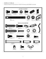
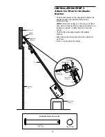
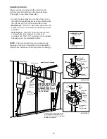
1. Strip 1/4" of insulation from one end of bell wire
and connect to the two screw terminals on back of
door control by color: white wire to 2 and white/red
wire to 1 (Fig. 3).
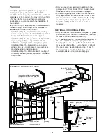
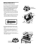
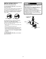
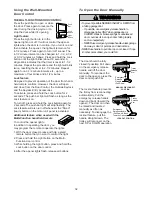
2. Remove white cover by gently pushing both
thumbs against upper corners of cover on back
side of door control (Fig. 4). Fasten with
6ABx1-1/4"self-tapping screws (standard
installation) or 6-32x1" machine screws (into gang
box) as follows:
• Drill and install bottom screw, allowing 1//8" to
protrude above wall surface.
• Position bottom of door control on screw head
and slide down to secure. Adjust screw for snug
fit.
• Install top screw with care to avoid
cracking plastic housing. Do not overtighten.
• Insert bottom tabs and snap on cover. (To
remove cover after mounting, gently pry at top
with paper clip or small flat head screwdriver.)
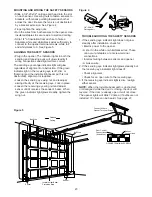
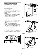
3. (Standard installation only) Run bell wire up wall
and across ceiling to motor unit. Use insulated
staples to secure wire in several places. Do not
pierce wire with a staple, creating a short or open
circuit.
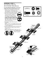
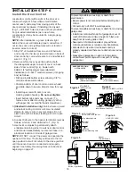
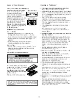
4. Connect bell wire to the opener terminal screws as
follows: white to 2 and white/red to 1. (Fig. 5).
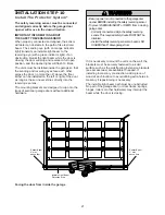
5. Use tacks or staples to permanently attach
entrapment warning label to wall near door control,
and manual release/safety reverse test label in a
prominent location on inside of garage door.
NOTE: DO NOT connect the power and operate the
opener at this time. The trolley will travel to the full
open position but will not return to the close position
until the sensor beam is connected and properly
aligned. See Safety Reversing Sensor Instructions
beginning on page 21.
2
1
RED WHT
Bell Wire
Terminal
Screws
Bottom Mounting Hole
Top Mounting Hole
6ABx1-1/4" Screw
(Standard installation)
Insulated Staples
Dry Wall Anchors
Screw 6-32x1"
(Pre-wired installation)
HARDWARE SHOWN
ACTUAL SIZE
Figure 2
To Replace
Insert Bottom Tabs First
PRE-WIRED INSTALLATION
24 Volt
Bell Wire
LOCK
LIGHT
LOCK
LIGHT
To Replace
Insert Bottom Tabs First
Figure 1
STANDARD
INSTALLATION
Single
Gang Box
Figure 3
MULTI-FUNCTION
DOOR CONTROL (BACK)
To prevent possible serious injury or death from
electrocution:
• Be sure power is not connected before installing door
control.
• Connect only to 24 VOLT low voltage wires.
To prevent possible serious injury or death from a closing
garage door:
• Install door control within sight of garage door, out of
reach of children at a minimum height of 5 feet, and
away from all moving parts of door.
• Never permit children to operate or play with door
control push buttons or remote control transmitters.
• Activate door only when it can be seen clearly, is
properly adjusted, and there are no obstructions to door
travel.
• Always keep garage door in sight until completely
closed. Never permit anyone to cross path of closing
garage door.
WARNING
CAUTION
WARNING
WARNING
ATTENTION
AVERTISSEMENT
AVERTISSEMENT
AVERTISSEMENT
Push
Bar
Light Button
Lock
Button
LOCK
LIGHT
Opener
Terminal Screws
KG
KG
1
3
9
7
5
1
3
9
7
5
3
1
RIGHT PANEL
Figure 5


