background image

*3-Button Remotes

If provided with your garage door opener, the large
button is factory programmed to operate it. Additional
buttons on any
Security

®

3-Button

remote or compact
remote can be
programmed to operate
other Security

®

garage door openers.

To Erase All Codes From Motor

Unit Memory

To deactivate any unwanted remote,
first erase all codes:

Press and hold the “learn” button on
motor unit until the learn indicator light
goes out (approximately 6 seconds). All
previous codes are now erased. Reprogram each
remote or keyless entry you wish to use.

KG

1

3

9

7

5

KG

1

3

9

7

5

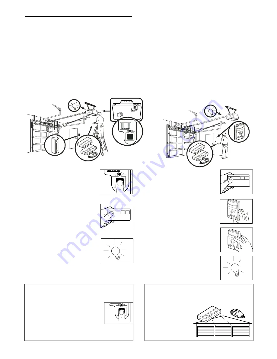
1. Press and release the “learn”

button on the motor unit. The
learn indicator light will glow
steadily for 30 seconds.

2. Within 30 seconds, press and

hold the button on the hand-held
remote

*

that you wish to operate

your garage door.

3. Release the button when the

motor unit lights blink. It has
learned the code. If light bulbs are
not installed, two clicks will be
heard.

PROGRAMMING

35

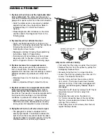
Your garage door opener has already been programmed at the factory to operate with your hand-held remote
control. The door will open and close when you press the large push button.

Below are instructions for programming your opener to operate with additional Security

®

remote controls.

1. Press and hold the button on the

hand-held remote

*

that you wish to

operate your garage door.

2. While holding the remote button,

press and hold the LIGHT button on
the Motion Detecting Door Control.

3. Continue holding both buttons while

you press the push bar on the
Motion Detecting Door Control (all
three buttons are held).

4. Release buttons when the motor

unit lights blink. It has learned the
code. If light bulbs are not installed,
two clicks will be heard.

NOTICE:

If this Security

®

garage door opener is operated with a non-rolling code transmitter, the technical

measure in the receiver of the garage door opener, which provides security against code-theft devices, will be
circumvented. The owner of the copyright in the garage door opener does not authorize the purchaser or
supplier of the non-rolling code transmitter to circumvent that technical measure.

To Add or Reprogram a Hand-held Remote Control

USING THE “LEARN” BUTTON

USING THE MOTION DETECTING DOOR CONTROL

LOCK

LIGHT

LOCK

LIGHT

Содержание Power Drive Security+ PD752CS

Страница 1: ...r s Manual Please read this manual and the enclosed safety materials carefully Fasten the manual near the garage door after installation The door WILL NOT CLOSE unless The Protector System is connected and properly aligned Periodic checks of the opener are required to ensure safe operation The model number label is located on the left side panel of your opener ...

Страница 2: ... Assembly 8 11 Assemble the rail and install the trolley 8 Fasten the rail to the motor unit and install the idler pulley 9 Install the chain cable 10 Tighten the chain 11 Installation 11 26 Installation safety instructions 11 Determine the header bracket location 12 Install the header bracket 13 Attach the rail to the header bracket 14 Position the opener 15 Hang the opener 16 Install the door co...

Страница 3: ...garage door Before you begin Disable locks Remove any ropes connected to garage door Complete the following test to make sure your garage door is balanced and is not sticking or binding 1 Lift the door about halfway as shown Release the door If balanced it should stay in place supported entirely by its springs 2 Raise and lower the door to see if there is any binding or sticking If your door binds...

Страница 4: ...ling in your garage If so a support bracket and additional fastening hardware may be required Installation Step 10 Depending upon garage construction extension brackets or wood blocks may be needed to install sensors Installation Step 10 Alternate floor mounting of the safety reversing sensor will require hardware not provided Trolley Header Wall Garage Door Header Bracket Straight Door Arm Emerge...

Страница 5: ...ING Support bracket fastening hardware is required See page 16 Safety Reversing Sensor Header Wall Gap between floor and bottom of door must not exceed 1 4 6 mm Wall mounted Door Control Rail Motor Unit Slack in chain tension is normal when garage door is closed ONE PIECE DOOR WITHOUT TRACK Header Bracket Trolley Straight Door Arm Emergency Release Rope Handle Door Bracket Curved Door Arm Header W...

Страница 6: ...justment is complete Carton Inventory Straight Door Arm Section Curved Door Arm Section Safety Labels and Literature 2 Conductor Bell Wire White White Red Chain and Cable Chain Spreader Hanging Brackets 2 Safety Reversing Sensors 1 Sending Eye and 1 Receiving Eye with 2 Conductor White White Black Bell Wire attached Door Bracket SECURITY 3 Button Remote Control with Visor Clip 2 Trolley Safety Sen...

Страница 7: ...1 1 Rope Lock Washer 5 16 7 Lag Screw 5 16 9x1 5 8 2 Hex Bolt 5 16 18x7 8 4 Clevis Pin 5 16 x1 1 4 1 Lag Screw 5 16 18x1 7 8 2 Screw 6ABx1 1 4 2 Screw 6 32x1 2 Clevis Pin 5 16 x1 1 2 1 Spacer 2 Washer 5 8 2 Spacer 2 Bolt 1 4 20x2 1 2 1 Bolt 1 4 20x1 3 4 1 Self Threading Screw 1 4 14x5 8 2 Hardware Inventory Separate all hardware and group as shown below for the assembly and installation procedures...

Страница 8: ...he opposite edge about 4 3 4 12 cm 1 Remove the straight door arm and hanging bracket packaged inside the front rail and set aside for Installation Step 5 and 12 NOTE To prevent INJURY while unpacking the rail carefully remove the straight door arm stored within the rail section 2 Align the rail sections on a flat surface as shown and slide the tapered ends into the larger ones Tabs along the side...

Страница 9: ...roximately 12 30 cm of cable through the window Allow it to hang until Assembly Step 5 Remove the tape from the idler pulley The inside center should be pre greased If dry regrease to ensure proper operation Place the idler pulley into the window as shown Insert the idler bolt from the top through the rail and pulley Tighten with a 3 8 lock washer and nut underneath the rail until the lock washer ...

Страница 10: ...ng over cap and onto pin notches until both pins are securely locked in place 3 With the trolley against the screwdriver dispense the remainder of the cable chain along the rail toward the motor unit into the slot on the chain spreader around the sprocket onto the chain spreader and continuing to the trolley assembly The sprocket teeth must engage the chain Figure 2 4 Check to make sure the chain ...

Страница 11: ...S To reduce the risk of SEVERE INJURY or DEATH WARNING WARNING WARNING 1 READ AND FOLLOW ALL INSTALLATION WARNINGS AND INSTRUCTIONS 2 Install garage door opener only on properly balanced and lubricated garage door An improperly balanced door may not reverse when required and could result in SEVERE INJURY or DEATH 3 All repairs to cables spring assemblies and other hardware MUST be made by a traine...

Страница 12: ...of the door NOTE If the total number of inches exceeds the height available in your garage use the maximum height possible or refer to page 13 for ceiling installation To prevent possible SERIOUS INJURY or DEATH Header bracket MUST be RIGIDLY fastened to structural support on header wall or ceiling otherwise garage door might not reverse when required DO NOT install header bracket over drywall Con...

Страница 13: ... Mark the vertical set of bracket holes do not use the holes designated for ceiling mount Drill 3 16 pilot holes and fasten the bracket securely to a structural support with the hardware provided Lag Screw 5 16 9x1 5 8 HARDWARE SHOWN ACTUAL SIZE CEILING HEADER BRACKET INSTALLATION Extend the vertical centerline onto the ceiling as shown Center the bracket on the vertical mark no more than 6 15 cm ...

Страница 14: ...E If the door spring is in the way you ll need help Have someone hold the opener securely on a temporary support to allow the rail to clear the spring Position the rail bracket against the header bracket Align the bracket holes and join with a clevis pin 5 16 x1 1 2 as shown Insert a ring fastener to secure Opener Carton or Temporary Support Garage Door OPTION WITH SOME EXISTING INSTALLATIONS Head...

Страница 15: ...for setting an ideal door to rail distance Remove foam packaging Raise the opener onto a stepladder You will need help at this point if the ladder is not tall enough Open the door all the way and place a 2x4 laid flat on the top section beneath the rail If the top section or panel hits the trolley when you raise the door pull down on the trolley release arm to disconnect inner and outer sections S...

Страница 16: ...ith the header bracket if the bracket is not centered above the door 7 Remove the 2x4 Operate the door manually If the door hits the rail raise the header bracket NOTE DO NOT connect power to opener at this time To avoid possible SERIOUS INJURY from a falling garage door opener fasten it SECURELY to structural supports of the garage Concrete anchors MUST be used if installing any brackets into mas...

Страница 17: ...trude above wall surface Position bottom of door control on screw head and slide down to secure Adjust screw for snug fit Install top screw with care to avoid cracking plastic housing Do not overtighten Insert bottom tabs and snap on cover NOTE The push bar may stick if the door control is not mounted on a smooth surface If a click is not heard when pressing the push bar loosen the two mounting sc...

Страница 18: ...gh the hole in the release arm of the outer trolley Adjust rope length so the handle is 6 feet 1 83 m above the floor Ensure that the rope and handle clear the tops of all vehicles to avoid entanglement Secure with an overhand knot NOTE If it is necessary to cut the rope heat seal the cut end with a match or lighter to prevent unraveling To prevent possible SERIOUS INJURY or DEATH from a falling g...

Страница 19: ...the black line wire to the screw on the brass terminal the white neutral wire to the screw on the silver terminal and the ground wire to the green ground screw The opener must be grounded Reinstall the cover To avoid installation difficulties do not run the opener at this time RIGHT WRONG To prevent possible SERIOUS INJURY or DEATH from electrocution or fire Be sure power is not connected to the o...

Страница 20: ...or Either can be installed on the left or right of the door as long as the sun never shines directly into the receiving eye lens The mounting brackets are designed to clip onto the track of sectional garage doors without additional hardware If it is necessary to mount the units on the wall the brackets must be securely fastened to a solid surface such as the wall framing Extension brackets see acc...

Страница 21: ...ip hugging the back edge of the track as shown in Figure 1 If your door track will not support the bracket securely wall installation is recommended Wall installation Figure 2 3 Place the bracket against the wall with curved arms facing the door Be sure there is enough clearance for the sensor beam to be unobstructed If additional depth is needed an extension bracket See Accessories or wood blocks...

Страница 22: ...t obstructed alignment is required Loosen the sending eye wing nut and readjust aiming directly at the receiving eye Lock in place Loosen the receiving eye wing nut and adjust sensor until it receives the sender s beam When the green indicator light glows steadily tighten the wing nut TROUBLESHOOTING THE SAFETY SENSORS 1 If the sending eye indicator light does not glow steadily after installation ...

Страница 23: ...follows depending on your door s construction Metal or light weight doors using a vertical angle iron brace between the door panel support and the door bracket Drill 3 16 fastening holes Secure the door bracket using the two 1 4 14x5 8 self threading screws Figure 2A Alternately use two 5 16 bolts lock washers and nuts not provided Figure 2B Metal insulated or light weight factory reinforced doors...

Страница 24: ...MINUM STEEL DOORS WITH GLASS PANEL ETC NOT PROVIDED ONE PIECE DOORS Please read and comply with the warnings and reinforcement instructions on the previous page They apply to one piece doors also Center the door bracket on the top of the door in line with the header bracket as shown Mark either the left and right or the top and bottom holes Metal Doors Drill 3 16 pilot holes and fasten the bracket...

Страница 25: ...m are above holes in straight arm disconnect straight arm Cut about 6 15 cm from the solid end Reconnect to trolley with cut end down as shown Bring arm sections together Find two pairs of holes that line up and join with bolts lock washers and nuts Pull the emergency release handle toward the opener at a 45 angle so that the trolley release arm is horizontal Proceed to Adjustment Step 1 page 27 T...

Страница 26: ...s 5 16 18 Lock Washers 5 16 Ring Fastener Straight Arm Bolts 5 16 18x7 8 Door Bracket Clevis Pin 5 16 x1 1 4 Curved Door Arm Press the Door Control push button The trolley will travel to the fully closed position Manually close the door and lift the door arm to the trolley The arm should touch the trolley just ahead of the door arm connector hole Refer to the fully closed trolley door arm position...

Страница 27: ...ed in Adjustment Step 2 If the door does not close completely Increase down travel Turn the down limit adjustment screw counterclockwise One turn equals 3 7 5 cm of travel If door still won t close completely and the trolley bumps into the pulley bracket page 4 try lengthening the door arm page 25 and decreasing the down limit If the opener reverses in fully closed position Decrease down travel Tu...

Страница 28: ... control clockwise Make small adjustments until the door completes a close cycle After each adjustment run the opener through a complete travel cycle Do not increase the force beyond the minimum amount required to close the door 2 Test the UP open force Grasp the door bottom when the door is about halfway through UP open travel The door should stop If the door is hard to hold or doesn t stop DECRE...

Страница 29: ...run the opener through 3 or 4 complete travel cycles to test adjustment If the unit continues to fail the Safety Reverse Test call for a trained door systems technician IMPORTANT SAFETY CHECK Test the Safety Reverse System after Each adjustment of door arm length limits or force controls Any repair to or adjustment of the garage door including springs and hardware Any repair to or buckling of the ...

Страница 30: ...ize is 100 watts maximum Security light feature Lights will also turn on when someone walks through the open garage door With a Multi Function Door Control this feature may be turned off as follows With the opener lights off press and hold the light button for 10 seconds until the light goes on then off again To restore this feature start with the opener lights on then press and hold the light but...

Страница 31: ...ning This door control contains a motion detector that will automatically turn on the light when it detects a person entering the garage This feature can be easily turned off for extended work light use Light feature Press the Light button to turn the opener light on or off It will not control the opener lights when the door is in motion If you turn it on and then activate the opener the light wil...

Страница 32: ... the code setting or replacing the battery THERE ARE NO OTHER USER SERVICEABLE PARTS Tested to Comply with FCC Standards FOR HOME OR OFFICE USE Operation is subject to the following two conditions 1 this device may not cause harmful interference and 2 this device must accept any interference received including interference that may cause undesired operation To prevent possible SERIOUS INJURY or DE...

Страница 33: ...r adjustments to force or travel limits The need for occasional adjustment for the force and limit settings is normal Weather conditions in particular can affect door travel Refer to Adjustment Step 1 Adjust the UP and DOWN Travel Limits Decrease down travel by turning down limit adjustment screw clockwise 5 My lights will not turn off when door is open The garage door opener is equipped with a se...

Страница 34: ...ontrol touch wires together If motor unit activates replace door control If motor unit does not activate disconnect door control wires from motor unit Momentarily short across red and white terminals with jumper wire If motor unit activates replace door control wires Symptom Sending indicator light glows steadily receiving indicator light is dim or flashing Realign receiving eye sensor clean lens ...

Страница 35: ...factory to operate with your hand held remote control The door will open and close when you press the large push button Below are instructions for programming your opener to operate with additional Security remote controls 1 Press and hold the button on the hand held remote that you wish to operate your garage door 2 While holding the remote button press and hold the LIGHT button on the Motion Det...

Страница 36: ...resent PIN then press and hold the button The opener light will blink twice Release the button 2 Press the new 4 digit PIN you have chosen then press Enter The motor unit lights will blink once when the PIN has been learned Test by pressing the new PIN then press Enter The door should move To set a temporary PIN You may authorize access by visitors or service people with a temporary 4 digit PIN Af...

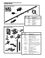
Страница 37: ...ton remote control 3 10A20 3V2032 Lithium battery 4 29B137 Remote control visor clip 5 41A2828 Emergency release rope and handle assembly 6 41B4494 1 2 Conductor bell wire white and white red 7 41A5047 1 Door bracket w clevis pin fastener 8 41A5047 2 Header bracket w clevis pin fastener 9 41A5034 Safety sensor kit receiving and sending eyes with 3 9 m 2 conductor bell wire 10 178B34 Straight door ...

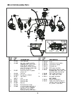
Страница 38: ...t 7 108D79 Lens 8A 30B530 Capacitor 56uF 8B 30B529 Capacitor 40uF 8C 41A5637 Resistor 9 41A3150 Terminal block w screws 10 41D5563 Universal replacement motor bracket assembly Complete with Motor worm bracket bearing assembly RPM sensor KEY PART NO NO DESCRIPTION 11 41A5633 2 Cover 12 41A2818 Limit switch drive retainer 13 41D3452 2 Limit switch assembly 14 41A2822 1 Interrupter cup 15 41C4398A RP...

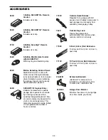
Страница 39: ... open fully 7710C 760C Outside Key Lock Opens the garage door automatically from outside when remote control is not handy Outside Quick Release Required for a garage with NO access door Enables homeowner to open garage door manually from outside by disengaging trolley 974C CLDM1C Garage Door Monitor Monitors the status of your garage door from inside your home 1 Button SECURITY Remote Control Incl...

Страница 40: ...end this product prepaid and insured to our service center for warranty repair You will be advised of shipping instructions when you call the toll free service number Please include a brief description of the problem and a dated proof of purchase receipt with any product that is returned fowarranty repair Products returned to Seller for warranty repair which upon receipt by Seller are confirmed to...

Страница 41: ...si que les consignes de sécurité Après la pose accrocher ce manuel près de la porte de garage pour s y reporter ultérieurement La porte NE SE FERMERA PAS si Le Système Protector n est pas branché et réglé correctement Pour un bon fonctionnement en toute sécurité de cet ouvre porte de garage le vérifier et le régler périodiquement L étiquette du numéro de modèle est située sur le panneau gauche de ...

Страница 42: ...stique 34 Programmation 35 36 Pour ajouter ou reprogrammer une télécommande à main 35 Pour effacer tous les codes 35 Télécommandes à trois boutons 35 Pour ajouter reprogrammer ou modifier un NIP d entrée sans clé 36 Pièces de réparation 37 38 Pièces d assemblage du rail 37 Pièces pour la pose 37 Pièces d assemblage du moteur 38 Accessoires 39 Pièces de réparation et service 40 Garantie 40 Lorsque ...

Страница 43: ...câbles poulies supports de porte ou leurs ferrures de montage lesquels sont tous sous une tension EXTRÊME Désactiver TOUTES les serrures et retirer TOUTES les cordes raccordées à la porte de garage AVANT de poser et d utiliser l ouvre porte de garage afin d éviter un emmêlement Préparation de votre porte de garage Avant de commencer Désactiver les serrures Retirer toute corde raccordée à la porte ...

Страница 44: ...et des fixations supplémentaires seront requises 10e opération de pose Suivant la construction du garage des supports de rallonge ou des blocs en bois peuvent être nécessaires pour poser les capteurs 10e opération de montage Le montage alternatif au sol du détecteur inverseur de sécurité nécessitera des fixations non fournies Y a t il une porte d accès au garage Dans la négative le dispositif de d...

Страница 45: ...vent être requises Se reporter à la page 16 Linteau Détecteur inverseur de sécurité Porte d accès L espace entre le plancher et le bas de la porte ne doit pas être supérieur à 1 4 de po 6 mm Commande de porte murale Lorsque la porte du garage est fermée il est normal que la chaîne dessine une courbe PORTE RIGIDE SANS GUIDES Câble Rail PORTE FERMÉE Support de linteau Biellette droite Poignée et cor...

Страница 46: ...mballage Biellette droite Biellette courbée Documentation et étiquettes de sécurité Fil de sonnerie blanc et blanc rouge à 2 conducteurs Chaîne et câble Écarteur de chaîne Supports de suspension 2 Capteurs d inversion de sécurité 1 œil de transmission et 1 œil de réception avec fil de sonnerie blanc et blanc noir à deux conducteurs fixé Support de la porte SECURITY Télécommande à trois boutons ave...

Страница 47: ...murs secs 2 Corde Vis 6AB x 1 1 4 po 2 Vis 6 32 x 1 po 2 Agrafe isolée 30 Axe de chape de 5 16 po x 1 po 1 Axe de chape de 5 16 de po x 1 1 4 de po 1 Axe de chape de 5 16 de po x 1 1 2 de po 1 Tire fond de 5 16 de po 18 x 1 7 8 de po 2 Boulon à tête bombée et collet carré de 1 4 de po 20 x 1 2 po 2 Tire fond de 5 16 de po 9 x 1 5 8 de po 2 Rondelle 5 8 po 2 Entretoise 2 Vis autotaraudeuse 1 4 po 1...

Страница 48: ...on 4 3 4 po 12 cm depuis l extrémité éloignée 1 Retirer la biellette droite les supports de suspension et l axe de chape insérés à l intérieur du rail avant et mettre de côté pour l installation à l étape 5 et 12 REMARQUE Pour éviter toute BLESSURE lors du déballage du rail retirer soigneusement le bras rectiligne de la porte inséré à l intérieur de la section du rail 2 Aligner les sections de rai...

Страница 49: ...onnement Placer la poulie dans la fenêtre comme illustré Insérer le boulon de tension depuis le dessus à travers le rail et la poulie Serrer à l aide d une rondelle frein de 3 8 po et d un écrou sous le rail jusqu à compression de la rondelle frein Faire tourner la poulie pour s assurer qu elle tourne librement Insérer un boulon de 1 4 po 20 x 1 3 4 dans le trou d arrêt du chariot à l avant du rai...

Страница 50: ...arteur de chaîne puis l enrouler autour du pignon dans l écarteur de chaîne et poursuivre l assemblage du chariot Les dents du pignon doivent engager la chaîne Figure 2 4 S assurer que la chaîne n est pas tordue puis la raccorder à l arbre fileté avec le maillon de raccord restant 5 Enfiler l écrou intérieur et la rondelle de blocage dans la tige filetée du chariot Figure 3 6 Insérer l arbre filet...

Страница 51: ...ser l ouvre porte de garage uniquement sur une porte de garage bien équilibrée et lubrifiée Une porte mal équilibrée peut ne pas remonter au besoin et pourrait provoquer des BLESSURES GRAVES ou LA MORT 3 Toutes les réparations aux câbles ensembles de ressort et autres ferrures de montage DOIVENT être confiées à un technicien formé en systèmes de porte AVANT de poser l ouvre porte 4 Désactiver tout...

Страница 52: ... de la porte REMARQUE Si le nombre total de pouces centimètres dépasse la hauteur disponible dans le garage utiliser la hauteur maximum ou se reporter à la page 13 pour la pose au plafond Porte articulée avec guide courbé Porte rigide avec guide horizontal Linteau Guide Point de course le plus haut Porte Porte Guide 2 po 5 cm Linteau Point de course le plus haut 2 po 5 cm Plafond non fini 2 x 4 MO...

Страница 53: ...afond Marquer la série verticale de trous de support Percer des avant trous de 3 16 de pouce et fixer fermement le support sur une solive avec les fixations fournies Tire fond de 5 16 de po 9 x 1 5 8 de po GRANDEUR RÉELLE DES FIXATIONS POSE DU SUPPORT DE LINTEAU AU PLAFOND Prolonger l axe vertical sur le plafond comme illustré Centrer le support sur l axe vertical à 6 pouces 15 cm au maximum du mu...

Страница 54: ... la porte gêne il faudra demander de l aide Demander à une personne de bien retenir l ouvre porte sur un support temporaire de façon que le rail ne touche pas le ressort Positionner le support du rail contre le support de linteau Aligner les trous des supports et les raccorder avec un axe de chape de 5 16 po x 1 1 2 po comme il est illustré Introduire un anneau d arrêt pour immobiliser Porte de ga...

Страница 55: ...er l emballage en mousse Lever l ouvre porte et le faire reposer sur un escabeau Si l escabeau n est pas assez haut demander de l aide Ouvrir complètement la porte et mettre un 2 x 4 à plat sur sa partie supérieure sous le rail Si le panneau ou la section du dessus vient en contact avec le chariot lorsqu on lève la porte tirer sur la biellette de dégagement du chariot pour dégager le chariot intér...

Страница 56: ... fonctionner la porte manuellement Si la porte frappe le rail lever le support de linteau REMARQUE NE PAS mettre l ouvre porte sous tension à ce stade Tire fond de 5 16 de po 18 x 1 7 8 de po Boulon hexagonal de 5 16 de po 18 x 7 8 de po Écrou de 5 16 de po 18 Rondelle frein de 5 16 de po GRANDEUR RÉELLE DES FIXATIONS Cornière Non fournie PLAFOND FINI Solive cachée Non fournis Boulon de 5 16 po 18...

Страница 57: ...xer à l aide de vis autotaraudeuses 6AB x 1 1 4 po installation standard ou de vis à métaux 6 32 x 1 po dans la boîte simple comme suit Percer et poser la vis inférieure en laissant 1 8 po 3 mm faire saillie du mur Placer le bas de la commande de porte par dessus la tête de vis et ajuster pour un ajustement serré Percer et poser la vis supérieure soigneusement afin d éviter de fissurer le boîtier ...

Страница 58: ...la longueur de la corde de façon que la poignée soit à environ 6 pieds 1 83 m du sol S assurer que la corde et la poignée ne risquent pas de toucher au capot d aucun véhicule pour éviter qu elle s emmêle Fixer la corde à l aide d un nœud simple REMARQUE Si la corde doit être coupée brûler légèrement l extrémité coupée pour empêcher qu elle s effiloche Ampoule standard de 100 W max Ampoule standard...

Страница 59: ...l blanc neutre sur la vis de la borne en argent puis le fil de terre sur la vis verte de terre L ouvre porte doit obligatoirement être mis à la terre Reposer le couvercle Pour éviter les difficultés pendant la pose ne pas faire fonctionner l ouvre porte pour le moment Pour prévenir d éventuelles BLESSURES GRAVES ou LA MORT par suite d électrocution ou d un incendie S assurer que l ouvre porte est ...

Страница 60: ...de lumière pendant que la porte se ferme la porte s arrêtera et remontera jusqu à la position entièrement ouverte et les lumières de l ouvre porte clignoteront 10 fois Les unités doivent être posées à l intérieur du garage de manière à ce que la cellule émettrice et la cellule réceptrice se fassent face l une l autre de part et d autre de la porte à pas plus de 6 po 15 cm au dessus du sol L une ou...

Страница 61: ...guide de porte ne supporte pas solidement le support une pose murale est recommandée Pose murale Figure 2 et 3 Placer le support contre le mur les bras courbés étant dirigés vers la porte S assurer qu il y a un dégagement suffisant et qu aucun obstacle n est dans le parcours du faisceau du détecteur Si une profondeur supplémentaire est nécessaire on peut employer un support de rallonge Se reporter...

Страница 62: ...bstruée aligner les deux détecteurs Desserrer l écrou de la cellule émettrice et ajuster de façon à ce qu elle vise directement la cellule réceptrice Serrer l écrou Desserrer l écrou de la cellule réceptrice et régler le détecteur jusqu à ce qu il reçoive le faisceau de la cellule émettrice Lorsque le témoin vert reste allumé serrer l écrou DÉPANNAGE DES DÉTECTEURS INVERSEURS DE SÉCURITÉ 1 Si lors...

Страница 63: ...eut également utiliser deux boulons de 5 16 po des rondelles de blocage et des écrous non fournis Figure 2B Portes métalliques isolées ou légères renforcées à l usine Percer des trous de fixation de 3 16 po Fixer le support de porte à l aide des vis autotaraudeuses Figure 3 Portes en bois Utiliser les trous supérieurs et inférieurs ou latéraux de support de porte Percer des trous de 5 16 po à trav...

Страница 64: ...garage Écrou 5 16 de po 18 PORTES RIGIDES Prière de lire et de suivre les avertissements et les instructions de renforcements à la page précédente Ils s appliquent également aux portes rigides Centrer le support de porte sur le dessus de la porte en l alignant avec le support de linteau comme il est illustré Repérer soit les trous de gauche et de droite soit les trous du haut et du bas Portes méta...

Страница 65: ...oupée vers le bas comme illustré Rapprocher les biellettes Aligner deux paires de trous et raccorder les deux biellettes avec les boulons les rondelles frein et les écrous Tirer sur la poignée de déclenchement d urgence en direction de l ouvre porte à un angle de 45 de façon que la biéllette de dégagement du chariot soit horizontale Passer à la 1re opération des réglages page 27 Le chariot se réen...

Страница 66: ...porte complètement fermée Écrous de 5 16 de po 18 Rondelles frein de 5 16 de po Anneau d arrêt Biellette droite Boulons de 5 16 de po 18 x 7 8 de po Support de la porte Axe de chape de 5 16 de po x 1 1 4 de po Biellette courbée À la main fermer complètement la porte puis soulever la biellette jusqu au chariot La biellette doit toucher le chariot juste devant son trou de raccordement Se reporter à ...

Страница 67: ... course de fermeture en tournant la vis de réglage DOWN dans le sens anti horaire Un tour complet de la vis correspond à 3 po 7 5 cm de course Si la porte ne se ferme toujours pas complètement et que le chariot heurte le support de la poulie page 4 essayer de rallonger le bras de la porte page 25 et de diminuer la course de fermeture Si l ouvre porte fait remonter la porte lorsqu elle est complète...

Страница 68: ...rmeture complet Après chaque réglage faire faire un cycle complet à l ouvre porte Ne pas augmenter la force au delà du niveau nécessaire pour fermer la porte 2 Vérification de la force d ouverture UP Pendant que la porte est environ à mi chemin de sa course d ouverture essayer de l arrêter à la main La porte doit s arrêter S il est difficile de retenir la porte ou si la porte ne s arrête pas DIMIN...

Страница 69: ...ARQUE Dans le cas d une porte articulée s assurer que les réglages ne forcent pas sur la biellette ni à l ouverture ni à la fermeture Se reporter aux illustrations de la page 25 Répéter l essai Lorsque la porte remonte sur la planche de 1 1 2 po 3 8 cm retirer l obstacle et faire faire 3 ou 4 cycles complets à l ouvre porte afin de vérifier le réglage Si l essai du système d inversion de sécurité ...

Страница 70: ... la commande de porte Multifonction sera activée Des ampoules de 100 watts maximum doivent être utilisées Éclairage Security Les lumières s allumeront également lorsqu une personne franchira la porte de garage ouverte Sur une commande de porte Multifonction cette fonction d éclairage peut être désactivée de la façon suivante les lumières fermées enfoncer et tenir le bouton d éclairage pendant 10 s...

Страница 71: ...pour inverser la porte durant le cycle de fermeture ou pour arrêter la porte pendant son ouverture Cette commande de porte contient un détecteur de mouvement qui allume automatiquement l éclairage lorsqu il détecte une personne pénétrant dans le garage On peut désactiver facilement catte fonction en vue d une utilisation prolongée des projecteurs de travail Fonction d éclairage Appuyez sur le bout...

Страница 72: ... s ouvre et se ferme complètement Au besoin régler les commandes de course et ou de force Se reporter aux pages 27 et 28 Répéter l essai du système d inversion de sécurité Procéder à tous les réglages nécessaires Se reporter à la 3e opération des réglages Deux fois par année Vérifier la tension de la chaîne Dégager d abord le chariot Régler la tension de la chaîne au besoin Se reporter à la page 1...

Страница 73: ...rôle de l inversion de sécurité après avoir procédé au réglage de la force ou des limites de course Le besoin de procéder à des réglages occasionnels des limites de courses et de la force est normal Les variations saisonnières en particulier peuvent altérer la course de la porte Se reporter à la 1ère opération de réglage Réglage des courses d OUVERTURE et de FERMETURE Diminuer la course de fermetu...

Страница 74: ...de de porte toucher les fils l un à l autre Si le moteur se met en marche remplacer la commande de porte Si le moteur ne se met pas en marche déconnecter les fils de la commande de porte du moteur Court circuiter momentanément les terminaux rouge et blancs à l aide d un câble de raccord Si le moteur se met en marche remplacer les fils de la commande de porte Symptôme Le témoin lumineux émetteur es...

Страница 75: ...anière à fonctionner avec la télécommande à main fournie La porte s ouvrira et se fermera lorsqu on appuiera sur le gros bouton poussoir Ci après se trouvent des instructions pour programmer votre ouvre porte en vue du fonctionnement avec d autres télécommandes Security KG 1 3 9 7 5 KG 1 3 9 7 5 REMARQUE Si cet ouvre porte de garage Security est utilisé avec une télécommande émettrice à code fixe ...

Страница 76: ...er sur ENTER La porte devrait bouger Pour définir un NIP temporaire Vous pouvez autoriser l accès aux visiteurs ou aux techniciens de service à l aide d un NIP temporaire à 4 chiffres Après un nombre programmé d heures ou un nombre programmé d utilisations ce NIP temporaire vient à expiration et n ouvre plus la porte On peut l utiliser pour fermer la porte une fois qu il a expiré Pour définir un N...

Страница 77: ... chape et fixation 8 41A5047 2 Support de linteau avec axe de chape et fixation 9 41A5034 Détecteur inverseur de sécurité cellules réceptrice et émettrice avec fil de sonnerie 3 pi 9 m à 2 conducteurs 10 178B34 Biellette droite 11 12B776 Support de suspension 12 178B35 Biellette courbée 13 41A5266 1 Support de détecteur inverseur de sécurité NON ILLUSTRÉS 41A5257 3 Sac de fixations de montage et d...

Страница 78: ...seur 8A 30B530 Condensateur du moteur 56uF 8B 30B529 Condensateur du moteur 40uF 8C 41A5637 Résistance 9 41A3150 Bornier à vis 10 41D3058 Moteur de rechange universel et support Comprend Moteur vis sans fin support roulement capteur de régime N DE RÉF PIÈCE DÉSIGNATION 11 41A5633 2 Couvercle 12 41A2818 Entraînement et dispositif de retenue d interrupteur de fin de courser 13 41D3452 2 Interrupteur...

Страница 79: ...érieur Pour ouvrir automatiquement la porte du garage de l extérieur sans la télécommande Détachement rapide d extérieur Nécessaire pour un garage SANS porte d accès Permet au propriétaire d ouvrir la porte de garage manuellement à partir de l extérieur en déconnectant le chariot 974C CLDM1C Système de détection d ouverture de porte de garage Permet de surveiller la plus grande porte de votre domi...

Страница 80: ...ice on vous avisera des instructions d expédition Veuillez inclure une brève description du problème et un reçu daté faisant preuve d achat avec tout produit renvoyé pour réparation en vertu de la garantie Les produits renvoyés au vendeur pour réparation en vertu de la garantie qui dès leur réception par le vendeur sont confirmés comme étant défectueux et couverts par cette garantie limitée seront...

Отзывы: