background image

OPERATOR 

REQUIRES EXTERNAL 

MONITORED ENTRAPMENT 

PROTECTION DEVICE

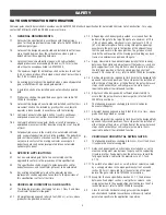
•  

THIS PRODUCT IS TO BE INSTALLED AND SERVICED BY A TRAINED GATE SYSTEMS 
TECHNICIAN ONLY. 

•  

This model is for use on vehicular passage gates ONLY and not intended for use on 
pedestrian passage gates. 

• 

This model is intended for use in Class I vehicular swing gate applications.

• 

Visit LiftMaster.com to locate a professional installing dealer in your area.

• 

This gate operator is compatible with MyQ

®

 and S 2.0

®

 accessories.

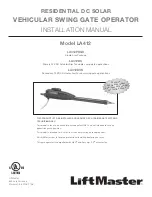
RESIDENTIAL DC SOLAR

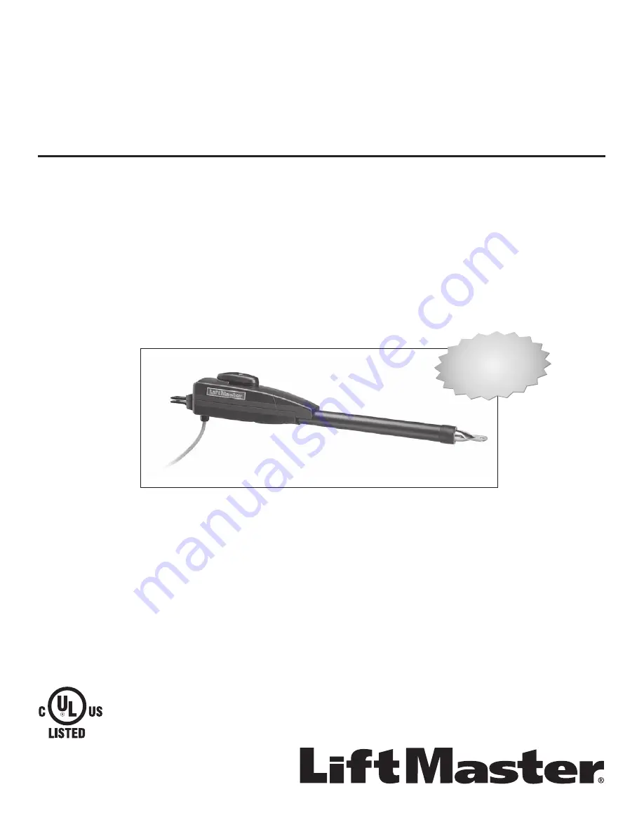
VEHICULAR SWING GATE OPERATOR

Model LA412

INSTALLATION MANUAL

LA412PKGU

Single Arm Package

LA412DC 

Primary 12 VDC Actuator Arm for single swing gate applications

LA412DCS


Secondary 12 VDC Actuator Arm for dual swing gate applications

LiftMaster
845 Larch Avenue
Elmhurst, IL 60126-1196

Содержание LA400DCS

Страница 1: ...Class I vehicular swing gate applications Visit LiftMaster com to locate a professional installing dealer in your area This gate operator is compatible with MyQ and Security 2 0 accessories RESIDENTIAL DC SOLAR VEHICULAR SWING GATE OPERATOR Model LA412 INSTALLATION MANUAL LA412PKGU Single Arm Package LA412DC Primary 12 VDC Actuator Arm for single swing gate applications LA412DCS Secondary 12 VDC A...

Страница 2: ...ICES 34 LOCKS 35 MISCELLANEOUS WIRING 35 MAINTENANCE 36 IMPORTANT SAFETY INFORMATION 36 MAINTENANCE CHART 36 BATTERIES 36 TROUBLESHOOTING 37 DIAGNOSTIC CODES 37 CONTROL BOARD LEDS 40 TROUBLESHOOTING CHART 41 APPENDIX 44 BRACKET TYPES 44 LIMIT SETUP WITH A REMOTE CONTROL 45 REPAIR PARTS 46 CONTROL BOX 46 GATE OPERATOR ARM 46 WIRING DIAGRAM 47 STANDARD CONTROL BOX 47 LARGE METAL CONTROL BOX 48 ACCES...

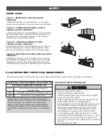
Страница 3: ...s is in accordance with the requirement however a single device is not required to cover both directions This operator is provided with Type A The installer is required to install additional entrapment protection devices in each entrapment zone HORIZONTAL SLIDE AND SWING GATE OPERATOR GATE OPERATOR ENTRAPMENT PROTECTION TYPES Type A Inherent built into the operator entrapment protection system Typ...

Страница 4: ...er activation must be located at least 6 feet 1 8 m away from any moving part of the gate and where the user is prevented from reaching over under around or through the gate to operate the controls Outdoor or easily accessible controls shall have a security feature to prevent unauthorized use Exception Emergency access controls only accessible by authorized personnel e g fire police may be placed ...

Страница 5: ...w astm org 3 1 2 All openings shall be designed guarded or screened from the bottom of the gate to the top of the gate or a minimum of 72 in 1 83 m above grade whichever is less to prevent a 2 1 4 in 57 mm diameter sphere from passing through the openings anywhere in the gate and in that portion of the adjacent fence that the gate covers in the open position The gate panel shall include the entire...

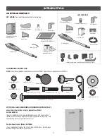
Страница 6: ...e for LA412DC Quantities are doubled for LA412DCS Flat Washer 3 8 3 Hex Nut 3 8 16 3 Lock Washer 3 8 3 Hex Bolt 5 16 18 x 1 1 2 1 Carriage Bolt 3 8 x 5 15 16 2 Hex Bolt 3 8 16 x 1 1 2 1 Hex Nut 5 16 18 1 Hairpin Clip 2 Flat Washer 5 16 1 Lock Washer 5 16 1 Pin 2 Keylock Cap Key 2 OPTIONAL ACCESSORIES ORDERED SEPARATELY Large Metal Control Box for Solar Applications Model XLSOLARCONTU Ideal for ins...

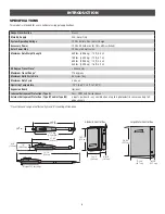
Страница 7: ...c 500mA max for ON SW switched Solar Power Max 12 Vdc at 30 watts max Maximum Gate Weight Length 850 lbs 385 6 kg 10 ft 3 0 m 750 lbs 340 2 kg 12 ft 3 7 m 650 lbs 294 8 kg 14 ft 4 3 m 550 lbs 249 5 kg 16 ft 4 9 m 90 Degree Travel Time 23 seconds Maximum Travel Range 115 degrees Maximum Daily Cycle Rate 50 cycles day Maximum Duty Cycle 4 min on Operating Temperature 20 C to 60 C 4 F to 140 F Expans...

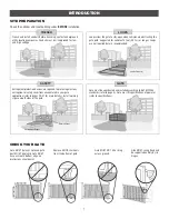
Страница 8: ... Check the national and local building codes BEFORE installation Trench and install conduit Before trenching contact underground utility locating companies Conduit must be UL approved for low and high voltage TRENCH Loops allow the gate to stay open when vehicles are obstructing the gate path Suggested for vehicles 14 feet 4 27 m or longer Loops are not required but are recommended CHECK YOUR GATE...

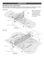
Страница 9: ...ng OVERVIEW OF TYPICAL INSTALLATION INTRODUCTION Identify your installation type refer to the Appendix in the back of the manual for more information All the illustrations on the following pages display a typical Left Hand Gate installation with a pull to open bracket For Push to Open applications refer to the Appendix DUAL GATE SINGLE GATE Photoelectric Sensors Photoelectric Sensors Photoelectric...

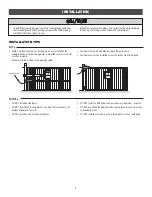
Страница 10: ...rinklers or any area that may expose the bottom of operator to water DO NOT install on uphill or downhill gates DO NOT install on ANY pedestrian passageways doorways or gates DO NOT over bend the operator cable Doing this will cause the wires to eventually break DO NOT weld the crossbar on just a few pickets or they could bend Operator Cable To AVOID damaging gas power or other underground utility...

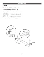
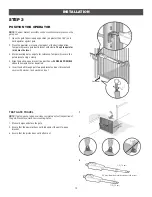
Страница 11: ...se The operator is now in manual mode 3 Assemble gate post bracket by placing pull to open bracket on top of post bracket 4 Insert the bolt through both brackets and secure with washer lock washer and nut 5 Attach post bracket assembly to operator using pins and hairpin clips 6 Attach gate bracket to operator using pins and hairpin clips Pin Pin Gate Bracket Hairpin Clip Hairpin Clip Post Bracket ...

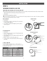
Страница 12: ... AND MARKING FOR THE GATE BRACKET Before proceeding begin with the gate in the fully closed position There are two methods for determining the proper location of the post brackets Paper template Located on the back page of this manual Must be cut out Tape measure Either method will work depending on preference NOTE There should only be a maximum of 4 10 2 cm from the center of the hinge to the edg...

Страница 13: ... bracket using a clamp 4 Align the pull to open bracket to a position as CLOSE AS POSSIBLE above the screwdriver or dowel rod 5 Insert hex bolt through pull to open bracket and post bracket and secure with washer lock washer and nut TEST GATE TRAVEL NOTE If gate does not open and close completely adjust the position of the gate bracket and mark new mounting holes 1 Manually open and close the gate...

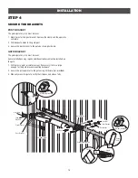
Страница 14: ...ns may require additional reinforcement be installed on the gate 1 Drill holes in gate or reinforcement if necessary that are large enough for the gate bracket mounting hardware 2 Secure the gate operator to the gate using hardware not provided 3 Manually move the gate to verify that it opens and closes fully Flat Washers Hex Nuts Lock Washers Carriage Bolts Welder Optional INSTALLATION Hex Nut Lo...

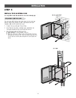
Страница 15: ...the screws and open the control box 2 Select the mounting holes according to your application and remove the knockouts using a screwdriver and hammer 3 Secure the control box to mounting surface A Wall or Column Use the provided screws 4 B Post Use U bolts and rubber washers not provided to ensure a watertight seal Make sure the U bolts do not protrude more than 3 4 inch from the control box becau...

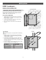
Страница 16: ...sure a watertight seal TYPE AND SIZE U BOLT OPENING Standard 3 Round Pipe 3 1 2 Standard 4 Square Post 4 Standard 6 Square Post 6 STEP 5 continued INSTALL THE CONTROL BOX LARGE METAL CONTROL BOX XLSOLARCONTU The control box MUST be mounted within 5 feet 1 52 m of the gate operator Mount the control box as high as possible for best radio reception Make sure the control box is level WALL OR COLUMN M...

Страница 17: ...TH GROUND ROD Use the proper earth ground rod for your local area The ground wire must be a single whole piece of wire Never splice two wires for the ground wire If you should cut the ground wire too short break it or destroy its integrity replace it with a single wire length 1 Install the earth ground rod within 3 feet of the control box 2 Run wire from the earth ground rod to the control box 3 C...

Страница 18: ...ATE THE WIRELESS FEATURE 1 Press and release the LEARN button on either control board The green XMITTER LED will light 2 Press and release the LEARN button again on the same control board The yellow NETWORK LED will light 3 Press and hold the LEARN button for 5 seconds The yellow NETWORK LED will blink operator will beep then turn off indicating successful deactivation Repeat the steps for the oth...

Страница 19: ... CABLE AND JUNCTION BOX Before digging contact local underground utility locating companies 1 Trench across driveway to bury the extension cable Use PVC conduit to prevent damage to cables 2 Open the junction box by removing screws 4 and set aside 3 Select holes to be used for mounting and knock out using a screwdriver and hammer Drill two holes in the bottom of the junction box large enough for t...

Страница 20: ...lly in dual gate installations one gate will need to open first and close second This would happen if there was an ornamental overhang on one gate or if using a solenoid lock for example This gate is called the Primary gate and needs to be connected to Gate 1 connections on the control board Thus it is preferred that the control box be installed on the same side as this gate If there is no appropr...

Страница 21: ...s not receive the signal from the device it will not run An entrapment zone is every location or point of contact where a person can become entrapped between a moving gate and a stationary object Your application may contain one or many entrapment zones Property owners are obligated to test entrapment protection devices monthly Use only LiftMaster approved entrapment protection devices refer to th...

Страница 22: ...erminals Switch set to CLOSE gate reverses fully when obstruction is sensed Switch set to OPEN gate reverses 4 seconds when obstruction is sensed EYE EDGE and COM Open or Close Direction Photoelectric Sensors or Edge Sensor the functionality is based on the switch settings located next to the terminals Switch set to CLOSE gate reverses fully when obstruction is sensed Switch set to OPEN gate rever...

Страница 23: ...ach below 4 F This is due to cold weather and a reduced number of hours of sunlight during the winter months Cycle rate may vary from solar chart for areas that reach below 32 F Solar panels should be cleaned on a regular basis for best performance to ensure proper operation INSTALLATION NOT AVAILABLE 1 1 2 3 SOLAR ZONES ZONE 1 6 Hours of Sunlight Day Ideal for solar application ZONE 2 4 Hours of ...

Страница 24: ... 25 50 53 27 29 30 48 51 25 27 50 39 42 17 19 100 19 21 20W SOLAR PANEL 6 100 100 76 85 31 35 25 100 100 67 76 24 27 30 100 100 65 73 22 25 100 78 92 33 41 200 32 44 30W SOLAR PANEL Three 10W 12V panels in parallel 6 100 100 100 100 47 57 25 100 100 100 100 39 48 30 100 100 100 100 37 46 100 100 100 66 86 17 200 83 100 22 39 STEP 10 continued SOLAR PANEL S SOLAR USAGE GUIDE Typical System Standby ...

Страница 25: ...the winter months when the sun sits lower in the sky The area around the solar panel s should be clear of shadows or obstructions to the sun for a 180 arc east to west Wire runs should be kept as short as possible The solar panel s can be located up to 100 feet 30 48 m from the operator using 16 AWG wire in any direction including elevating it DO NOT install solar panel near potential shading or o...

Страница 26: ...rol board will power up NOTE You may see a small spark when plugging the J15 plug into the board J15 BATT DC POWER Control Board J15 Plug Solar Panel Solar Panel Optional Solar Panel Optional Solar Panel Black Wire Red Wire Diode Mounted Panel Must Face South Mounting Surface Mounting Surface INSTALL THE SOLAR PANEL 1 Position solar bracket on mounting surface Mark and drill holes 2 Insert two bol...

Страница 27: ... limits is adjusted the other control may also need adjustment After ANY adjustments are made the safety reversal system MUST be tested Gate MUST reverse on contact with a rigid object LIMIT AND FORCE ADJUSTMENT INTRODUCTION Your operator is designed with electronic controls to make travel limit and force adjustments easy The adjustments allow you to program where the gate will stop in the open an...

Страница 28: ... limit is being set 5 Press and hold the MOVE GATE button to move the gate to the other limit 6 Press and release the SET CLOSE or SET OPEN button depending on which limit is being set The operator will exit limit setting mode 7 Cycle the gate open and close using the TEST BUTTONS This automatically sets the force 8 For dual gates set the Gate switch to the 2 position and repeat steps 2 7 When lim...

Страница 29: ...on on page 27 OPEN Limit CLOSE Limit 3 2 1 60 180 MIN MAX ING BATT LOW ACC PWR OVLD DIAG C SE REVERSAL FORCE NETWORK OPEN CLOSE STOP TEST BUTTONS RSAL RCE XMITTER NETWORK 2 1 SET OPEN SET CLOSE PRESS RELEASE OPEN CLOSE STOP TEST BUTTONS RSAL RCE XMITTER NETWORK The operator is equipped with an automatic obstruction sensing feature If the gate encounters an obstruction during motion the operator wi...

Страница 30: ...asonable protection against harmful interference in a residential installation This equipment generates uses and can radiate radio frequency energy and if not installed and used in accordance with the instructions may cause harmful interference to radio communications However there is no guarantee that interference will not occur in a particular installation If this equipment does cause harmful in...

Страница 31: ...ateway 3 Create an online account by visiting www myliftmaster com 4 Register the LiftMaster Internet Gateway 5 Use an internet enabled computer or smartphone to add devices The LiftMaster Internet Gateway will stay in learn mode for three minutes 6 Press the Learn button twice on the primary operator the operator will beep as it enters learn mode The LiftMaster Internet Gateway will pair to the o...

Страница 32: ...ARN button is for programming remote controls and the network 7 TIMER TO CLOSE dial The TIMER TO CLOSE TTC dial can be set to automatically close the gate after a specified time period The TTC is factory set to OFF If the TTC is set to the OFF position then the gate will remain open until the operator receives another command from a control Rotate the TIMER TO CLOSE dial to the desired setting The...

Страница 33: ...the release lever 3 Remove the key and store in a safe place The operator is now engaged RESET BUTTON The reset button is located on the side of the control box and serves several functions Press the reset button to stop a moving gate during a normal open close cycle like a stop button Press the reset button once while the gate is in open position to disable the Timer to Close The gate will stay i...

Страница 34: ...bent in an awkward position Remove any obstructions Press the reset button to shut off the alarm and reset the operator After the operator is reset normal functions will resume The operator alarm will beep 3 times with a command if the battery is low REMOTE CONTROL SINGLE BUTTON CONTROL SBC FUNCTIONALITY Once the remote control has been programmed the operator will operate as follows When gate is ...

Страница 35: ... pauses Timer to Close at OPEN limit SHADOW 2 Terminals This input is used for external shadow loop detector when loop is positioned under the swing of the gate Holds open gate at open limit Only active when the gate is at the OPEN limit disregarded at all other times Pauses Timer to Close at OPEN limit INTERRUPT 2 Terminals This input is used for photoelectric sensors and external interrupt loop ...

Страница 36: ...D 12 Vdc voltage out to power accessories always ON Com SBC main control board Single Button Control Station Fire Department Com Fire Dept Acc Power 12 Vdc Com main control board Accessory Power Switched Accessory Power Unswitched Acc Power 12 Vdc Com LOCKS MAGLOCK 2 Terminals N C and COM Relay contact output Normally closed N C output for maglocks Relay activates prior to motor activation and dur...

Страница 37: ...the operator or in the area near the operator MUST NOT be performed until disconnecting the electrical power AC or solar and battery and locking out the power via the operator power switch Upon completion of maintenance the area MUST be cleared and secured at that time the unit may be returned to service Disconnect power at the fuse box BEFORE proceeding Operator MUST be properly grounded and conn...

Страница 38: ...ntrol board it is recommended that you unplug the J15 plug then press and hold the OPEN button until Er shows on the display CODE NUMBER The second number shown after the code sequence number is the code itself 31 99 example 31 Refer to the chart on the following page for an explanation of each code CODE SEQUENCE NUMBER The first number shown is the most recent code example 01 The display will sho...

Страница 39: ...Too much voltage on the battery Check harness Make sure there is NOT a 24V battery on a 12V system YES 41 Battery overcurrent Possible short of the battery charge harness Check harness Make sure you do NOT have a 12V battery on a 24V system YES 42 No battery at boot up Check battery connections and installation Replace batteries if depleted to less than 20V on a 24V system or less than 10V on a 12...

Страница 40: ...or canceling TTC 72 OPEN EYE EDGE triggered causing reversal or preventing opening 73 CLOSE EYE INTERRUPT triggered causing reversal preventing close or resetting TTC IF an obstruction occurred no action required If an obstruction did NOT occur check alignment inputs and wiring on expansion board NO 74 CLOSE EYE EDGE triggered causing reversal and preventing close or canceling TTC 75 OPEN EYE EDGE...

Страница 41: ...ve BLINK Input active on other operator LOCK OFF Maglock relay inactive ON Maglock relay active STATUS LEDS INPUT POWER OFF OFF state ON AC charger or Solar power available BATT CHARGING OFF Not charging ON Three stage battery charging TIMER OFF The timer is disabled ON The timer is enabled MEDIUM BLINK 1 blink per second The timer is running FAST BLINK 2 blinks per second The timer is paused FAST...

Страница 42: ...gh its entire range limit to limit Repair gate as needed Operator does not respond to a wired control command example Open Close SBC etc a Check Open and Close command input LEDs b Stop button is active c Reset button is stuck d If on battery power only low or dead batteries e Entrapment Protection Device active f Vehicle loop detector or vehicle probe active a Check all Open and Close inputs for ...

Страница 43: ... wiring Retest that obstructing photoelectric sensor causes moving gate to stop and may reverse direction b Replace defective photoelectric sensor Retest that obstructing photoelectric sensor causes moving gate to stop and may reverse direction Edge Sensor does not stop or reverse gate a Incorrect edge sensor wiring b Defective edge sensor a Check edge sensor wiring Retest that activating edge sen...

Страница 44: ... measuring accessory voltage after every new connection b Replace defective control board Quick Close not working correctly a Quick Close setting incorrect b Interrupt loop detector c Defective Expansion board a Check that Quick Close setting is ON b Check operation of Interrupt Loop detector c Replace defective Expansion board Anti Tailgating not working correctly a Anti Tail setting incorrect b ...

Страница 45: ...44 BRACKET TYPES Right Hand Gate Left Hand Gate Right Hand Gate PULL TO OPEN Left Hand Gate PUSH TO OPEN APPENDIX ...

Страница 46: ... limit 8 Cycle the gate open and close This automatically sets the force When limits are set properly the operator will automatically exit limit setting mode ADJUST THE LIMITS If the limits have already been set the operator will exit the limit setting mode after resetting each limit Set the Close Limit Only 1 Press and release the SET OPEN and SET CLOSE buttons simultaneously to enter limit setti...

Страница 47: ...N K74 36806 5 Metal Control Box Only K94 36891 J15 Harness K77 36541 Antenna LA412CONTU Standard Plastic Control Box with control board GATE OPERATOR ARM ITEM PART NUMBER DESCRIPTION 1 LA412DC Primary Arm 2 41ASWG 442SA Release Lever 3 41ASWG 0594SA Motor with Limit Switch Harness 4 41ASWG 0014SA Rear Connector 5 41ASWG 0597SA Cable 12 V with Connector NOT SHOWN 41ASWG 0119 Release Key K77 19130 H...

Страница 48: ...y 12V 7AH Battery Black Red 20A To J15 Primary Operator Secondary Operator Two 12V Solar Panels in Parallel Black Red Blocking Diode Photoelectric Sensors WIRING DIAGRAM STANDARD CONTROL BOX To protect against fire and electrocution DISCONNECT power AC or solar and battery BEFORE installing or servicing operator For continued protection against fire Replace ONLY with fuse of same type and rating ...

Страница 49: ...tric Sensors Piezo Alarm White White Blue Reset Switch Red Black Primary Operator Secondary Operator WIRING DIAGRAM LARGE METAL CONTROL BOX To protect against fire and electrocution DISCONNECT power AC or solar and battery BEFORE installing or servicing operator For continued protection against fire Replace ONLY with fuse of same type and rating ...

Страница 50: ... key ring and fastening strip Model 890MAX SECURITY 2 0 LEARNING REMOTE CONTROLS One button can control a gate operator and the other s can control garage door s It can also be programmed to Security or Security 2 0 code format Models 892LT and 894LT KEYLESS ENTRY Enables homeowner to operate gate operator from outside by entering a 4 digit code on a specially designed keypad Model 877MAX ENTRAPME...

Страница 51: ...ing this product Then send this product pre paid and insured to our service center for warranty repair You will be advised of shipping instructions when you call Please include a brief description of the problem and a dated proof of purchase receipt with any product returned for warranty repair Products returned to Seller for warranty repair which upon receipt by Seller are confirmed to be defecti...

Страница 52: ...1 2 3 4 5 6 7 7 6 5 4 3 2 1 TEMPLATE FOR POST BRACKET MOUNTING 01 37831C 2015 LiftMaster All Rights Reserved 845 Larch Avenue Elmhurst Illinois 60126 1196 LiftMaster com ...

Отзывы: