background image

Chapter 2 

Chapter 2  

Hardware Setup 

If your motherboard has already been installed in your computer you may still need 

to refer to this chapter if you plan to upgrade your system's hardware. 


This motherboard is electrostatic sensitive. Do not touch without 

wearing proper safety gadget and make sure to disconnect the power 

cable from the power source before performing any work on your 

motherboard. Not doing so may result in electrical shock! 

2-1  Installing a CPU Processor for Socket 478 

The Intel® Socket 478, designed for the Pentium 4 processor, has been incorporated 

as a standard motherboard specification. This motherboard will support Intel® 

Pentium 4 CPUs with its embedded Hyper-Threading technology. To insert your 

CPU into Socket 478 please follow the steps below: 

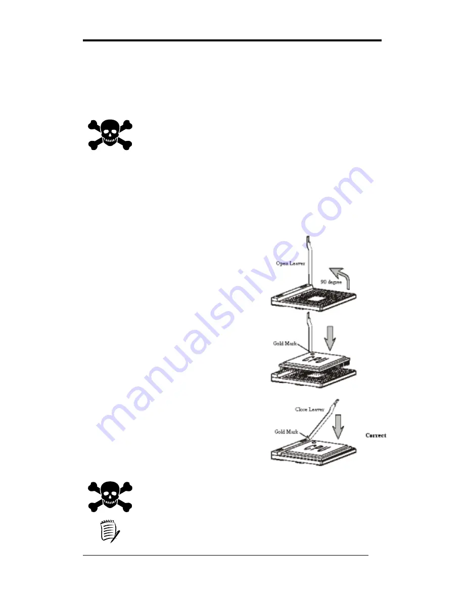
1.  Locate the 478-pin CPU socket on the motherboard. 

2.  Unlock the socket by pressing the lever sideways, and 

then open it up to a 90-degree angle. 

3.  Locate a Gold Mark on the top surface of the CPU, 

which is close to one of the CPU corners. The same 

corner will also be cut off, leaving a noticeable notch 

in the CPU's corner. These markings indicate Pin 1 on 

the CPU. 

4. Gently insert the CPU with Gold Mark/Pin 1 at the 

same corner of Socket 478, which is located close to 

the end of the lever. Allow the weight of the CPU to 

push itself into place. Do not apply extra pressure as 

doing so may result in damaging your CPU. 

5. When the CPU is correctly inserted, close the lever 

with your finger on to of the CPU to make sure the 

CPU is properly embedded into the socket. 

6.  Insert an appropriate heat sink and fan for proper Heat 

dispatch. 


Installing a standard Intel® specified heat sink with cooling fan is 

necessary for proper heat dissipation from your CPU. Failing to install 

these items may result in overheating and possible burnout of your CPU. 


In order to boot up with a newly installed CPU, AC Power must be 

switched off before installation. 


4

Содержание 9EJL4

Страница 1: ...9EJL4 Intel Socket 478 Intel 845PE ICH4 ATX Motherboard User s Guide Version 1 0...

Страница 2: ...5 of the FCC Rules Operation is subject to the following two conditions 1 This device may not cause harmful interference 2 This device must accept any interference received including interference that...

Страница 3: ...th FCC regulations Changes or modifications to this unit not expressly approved by the party responsible for compliance could void the user s authority to operate this equipment Canadian Department of...

Страница 4: ...3 2 Advanced BIOS Features 17 3 3 Advanced Chipset Features 20 3 4 Integrated Peripherals 22 3 5 Power Management Setup 25 3 6 PNP PCI Configurations 28 3 7 Frequency Voltage Control 29 3 8 Load Fail...

Страница 5: ...el audio subsystem via AC link With external high quality CMedia 9739A 6 channel AC 97 Codec Complete software driver supports for Windows OS Ultra DMA 66 100 PCI IDE Controller Supports two IDE ports...

Страница 6: ...h ROM Award system BIOS supports PnP APM DMI ACPI Multi device booting features 1 2 Package Contents This product comes with the following components 1 Motherboard x 1 2 40 Pin UDMA 100 IDE Cable x 1...

Страница 7: ...Chapter 1 1 3 9EJL4 Motherboard Layout 3...

Страница 8: ...the lever sideways and then open it up to a 90 degree angle 3 Locate a Gold Mark on the top surface of the CPU which is close to one of the CPU corners The same corner will also be cut off leaving a...

Страница 9: ...g to your processor s specifications After turning on your system s power enable the CMOS Setup Utility by pressing Delete key when your BIOS identification screen appears Then go to Frequency Voltage...

Страница 10: ...dules to meet your own needs To install your DDR Modules please follow the following steps 1 Unlock a DIMM socket by pressing the retaining clips outward The DDR Modules has only one notch at the cent...

Страница 11: ...very last part connected when assembling a system The ATX power supply provides a single 20 pin connector interface which incorporates standard 5V 12V optional 3 3V and Soft power signals The Soft pow...

Страница 12: ...ction properly again Unlike conventional fuses the poly fuse does not have to be replaced relieving the user from such inconveniences CN1A Front Panel Connector 1 PWR SW Over ride Power Button Connect...

Страница 13: ...mouse is touched The system resumes in different ways as defined by Power Management Setup screen in BIOS For Green LED connector please refer to Section 2 6 CBOX 2 4 RESET System Reset Switch Connect...

Страница 14: ...connecting 40 pins of ATAPI devices IDE 1 only connects two IDE devices Primary Master Slave IDE 2 only connects two IDE devices Secondary Master Slave JP1 CMOS Clear Jumper Pin Definition 1 2 Normal...

Страница 15: ...and then press Enter to continue 5 Set the system configuration in the Standard CMOS Setup menu JP6 Enable Disable USB 0 1 Device Wake Up Jumper Pin Definition 1 2 Disable default 2 3 Enable JP6 USB 0...

Страница 16: ...wiring and plugging may vary depending on the manufacturer On standard fans the red is positive 12V the black is ground and the yellow wire is the rotation signal Connect the north bridge cooling fan...

Страница 17: ...ownership costs Magic Packet technology is designed with WOL capability to LAN controller This header is used to connect an add in NIC Network Interface Card that provides WOL function to the motherbo...

Страница 18: ...onnectors is also included for an optional USB Adaptor USB 2 3 and 4 5 CN24 CBOX 2 Front Audio Connector This connector gives you the option of a front panel audio jack cable ext to be plugged into a...

Страница 19: ...d BIOS setup program press Delete when you Power on or reboot the computer system The primary screen as shown in Figure 3 1 is a list of the menus and functions available in the setup program Select t...

Страница 20: ...e system Do not skip this function as all of your timed events such as power management saving files etc are based on this timer IDE Primary Secondary Master Slave This category identifies up to four...

Страница 21: ...you set it as enabled you receive a warning message if a program specifically a virus attempts to write to the boot sector or the partition table of the hard disk drive Many disk diagnostic programs...

Страница 22: ...above does not include booting from floppy drive B This function is useful if floppy drives B and A are of a different format and you want to boot from floppy drive B Boot up Floppy Seek This is a se...

Страница 23: ...oller mode Enabling APIC mode will increase the available IRQ resources for the system Available options are Enabled and Disabled MPS Version Control For OS This item allows you to select which MPS Mu...

Страница 24: ...tures setup is lengthy highly technical and beyond the scope of this manual Below are some abbreviated descriptions of the functions in this setup menu DRAM Timing Selectable The function allows you t...

Страница 25: ...ed Transaction Available options Disabled and Enabled Delay Prior to Thermal Available options None 4 8 16 and 32 min AGP Aperture Size MB This function determines the amount of system memory that is...

Страница 26: ...lave PIO The four IDE PIO programmed Input Output fields let you set a PIO mode 0 4 for each IDE device that the internal PCI IDE interface supports Modes 0 through 4 provide successively increased pe...

Страница 27: ...ding interrupt for the first and second serial ports Available options are 3F8 IRQ4 2E8 IRQ3 3E8 IRQ4 2F8 IRQ3 Disabled and Auto 3 UR2 Duplex Mode Available options Half and Full 4 Onboard Parallel Po...

Страница 28: ...PS 2 keyboard will no longer work USB 2 0 Controller This entry is for disable enable EHCI controller only This BIOS itself may may not have high speed USB support If the BIOS has high speed USB suppo...

Страница 29: ...entering power saving modes Video Off Method This function serves as both screen and power saver for monitors See the next function Video Off After for setting the video timer 1 Blank BIOS will switc...

Страница 30: ...ate the system and perform tasks This assignment is compliant with the APM 1 2 compliant operating systems Suspend Mode The Power Management function is set as Enabled to activate this function If the...

Страница 31: ...bled and Disabled 5 Power On by Alarm When enabled this setting allows the system to turn back on at specified date of the month User must designate date of month and time of day This function is only...

Страница 32: ...tems in the setup menu for assigning IRQ DMA When set to Auto the system BIOS will refer to ESCD for all legacy information ESCD Extended System Configuration Data provides a detailed format of the co...

Страница 33: ...For Please leave the default system setting Auto for a stable system operation CPU Clock Ratio This feature allows user to manually configure your CPU clock ratio according to your processor s specifi...

Страница 34: ...3 1 If user defined BIOS settings are corrupted and therefore unusable these defaults will be loaded automatically when you turn on the computer 3 10 Supervisor Password User Password Setting There ar...

Страница 35: ...Setup If you select this and type Y for Yes followed by Enter the values entered in the setup utilities will be recorded in the CMOS memory of the BIOS chip 3 12 Exit Without Saving Selecting this opt...

Страница 36: ...Bus Mastering Drivers 2 Click Next to start software installation 3 Click Yes to accept the license agreement 4 Please select Next 5 Please select Finish after restart 4 2 Ultra ATA storage driver Se...

Страница 37: ...setup 4 5 USB 2 0 Driver 1 Click USB 2 0 Driver 2 Click Next to start software installation 3 Please click Next to continue 4 Please click Yes to accept the license agreement 5 Please click OK to con...

Страница 38: ...All rights are reserved for the products and corporate names logos that appear in this manual to their original owners CHAINTECH reserves all the rights to change this manual All information is subjec...

Страница 39: ...5 rue de Rome 93561 Rosny Sous Bois Cedex France Tel 33 1 4855 5940 Fax 33 1 4855 5942 E mail infos chaintech france com For China CHAINTECH SHENZHEN Room 301 Nanguang Building No 1004 Huafu Rd Futian...

Отзывы: