CHAINTECH 7VJS Скачать руководство пользователя страница 12

Chapter 2 


19 

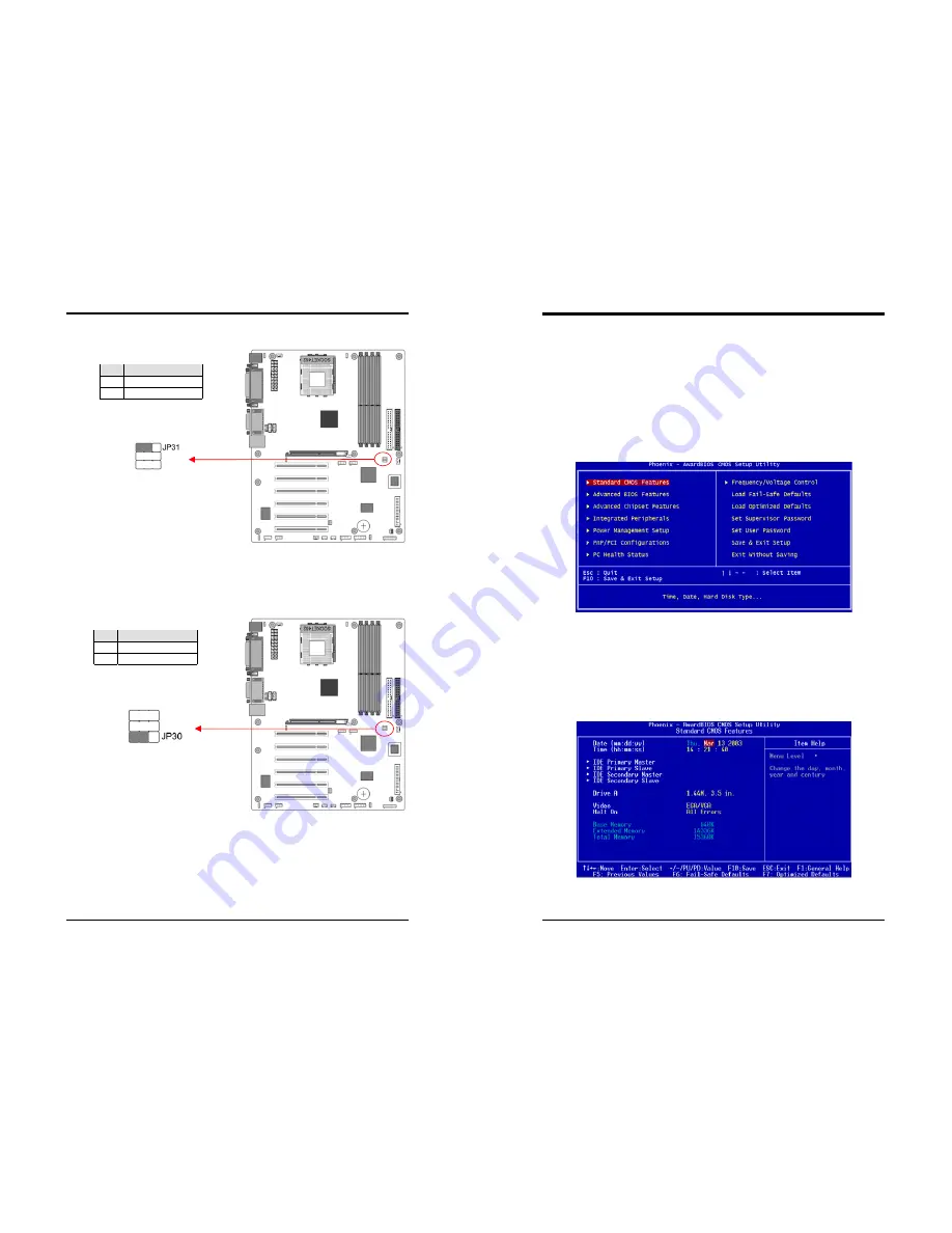
JP31 (166MHz Clock Frequency) 


This jumper allows users to configure the CPU clock frequency at 166MHz. 

Setting the jumper to pin 2-3, the External Clock Frequency will automatically 
disable.    To enable JP3 function, please set the jumper cap to pin 1-2. 


JP30 (ROM SIP) 


The ROM Serial Initialization Packet (SIP) function is for advanced user to use the 

Boot ROM to boot up the system. For normal booting operation you must set the 
jumper cap to pin 1-2 Hardware(default). 

Pin 

Definition 

1-2 

JP3 Enable 

2-3 

166 MHz 

Pin 

Definition 

1-2  Hardware (default) 
2-3 

Boot ROM 

Chapter 3     

20  

Chapter 3  

BIOS Setup Program 

Phoenix-Award BIOS ROM has a built-in setup program that allows users to modify 

the basic system configuration.  This information is stored in CMOS RAM so that it 
can retain the setup information, even when the power is turned off.   

To enter the 

Phoenix-Award BIOS

 setup program press the [Delete

 key

] when you 

Power on

 or 

reboot

 the computer system. The primary screen as shown in Figure 3-1 is 

a list of the menus and functions available in the setup program.   Select the desired 
item by your arrow keys and press enter to make the changes.  Operating commands 
are located at the bottom of this and all other BIOS screens.  When a field is 
highlighted, on-line help information is displayed on the right side of the screen. 


Figure 3-1 


3-1  Standard CMOS Setup 

The Standard CMOS Setup allows users to configure system components such as 

hard disk drive, floppy disk drive and video display as well as date, time and boot-up 
error signaling.  This configuration menu should be changed when installing a 
motherboard for the first time, changing hardware in your system such as the HDD, 
FDD, video display, or when the CMOS data has been lost or contaminated.    Choose 
the Standard CMOS Setup option from the CMOS Setup Utility menu (Figure 3-1) to 
display the following screen. 


Figure 3-2 

Содержание 7VJS

Страница 1: ...that complies with 47 CFR Parts 2 and 15 of the FCC Rules Operation is subject to the following two conditions 1 This device may not cause harmful interference 2 This device must accept any interferen...

Страница 2: ...e without notice and does not represent a commitment on the part of the vendor No warranty or representation either expressed or implied is made with respect to the quality accuracy or fitness for any...

Страница 3: ...ll common multi tasking operating systems On board IDE RAID Controller Optional Promise PDC20276 IDE RAID controller extra two UltraDMA 66 100 133 IDE ports with RAID 0 1 Embedded USB 2 0 Host Control...

Страница 4: ...Chapter 1 3 1 3 7VJS Motherboard Diagram Chapter 1 4 1 4 7VJS Motherboard Layout...

Страница 5: ...U parameters through an easy to use BIOS setup procedure It is no Chapter 2 6 longer necessary to make many jumper settings as on conventional motherboard After installing all your hardware into your...

Страница 6: ...d or USB connector can function properly again Unlike conventional fuses the poly fuse does not have to be replaced relieving the user wasted time and inconvenience Chapter 2 8 CN1A Front Panel Connec...

Страница 7: ...er supply from the power source 2 Set the jumper cap at location 2 3 for 5 seconds and then set it back to the default position 3 Connect the system s power and then start the system 4 Enter BIOS s CM...

Страница 8: ...N3 Auxiliary Audio in Connector This connector is for AUX Audio Device Chapter 2 12 CN4B AC3 Center Surround Bass Connector This connector must be connected to a 6 channel bracket Optional JP6 Power O...

Страница 9: ...and 4 5 Pin Definition 1 2 Disable default 2 3 Enable Chapter 2 14 CN24 Front Panel Audio Connector This connector give you the option of a front panel audio jack cable ext to be plug into a special c...

Страница 10: ...ment Menu to use this function This header is used to connect an add in NIC Network Interface Card which gives WOL capability to the motherboard Pin Definition 1 2 Disable default 2 3 Enable Chapter 2...

Страница 11: ...is red LED Pin Definition 1 2 Default 2 3 OEM Chapter 2 18 CN7 Smart Card Reader Connector This connector must be connected to an optional Smart card reader JP3 External Clock Frequency This jumper al...

Страница 12: ...To enter the Phoenix Award BIOS setup program press the Delete key when you Power on or reboot the computer system The primary screen as shown in Figure 3 1 is a list of the menus and functions avail...

Страница 13: ...on to reduce the amount of time required to run the POST Power On Self Test BIOS will save time by skipping some items during POST It is recommended that you disable this setting Discovering a problem...

Страница 14: ...ration Precharge to Active Trp This item controls the idle clocks after issuing precharge command to the DRAM Active to Precharge Tras This item controls the number of DRAM clocks used for DRAM parame...

Страница 15: ...contains a DMA driver If both your hard drive and software support Ultra DMA select Auto to enable BIOS support VIA OnChip PCI Device This section provides information for setting onboard device By ch...

Страница 16: ...s set in this user configurable field This feature does not affect SCSI hard drives Suspend Mode The Power Management function must not be set to disabled to enable this function If the system runs in...

Страница 17: ...3 7 PNP PCI Configurations PNP OS Installed If you want to install a PNP compatible OS such as Windows 95 set to Yes Chapter 3 30 Reset Configuration Data If you want to reset CMOS IRQ divide hardwar...

Страница 18: ...on the computer Chapter 3 32 3 10 Load Optimized Defaults Load Optimized Defaults loads the default system values directly from the CMOS Setup Utility menu Figure3 1 If the stored record created by th...

Страница 19: ...33 Chapter 4 DRIVER Setup Please insert VIA Series CD to CDROM Figure 4 1 4 1 VIA Service Pack Setup 1 Please select VIA Service Pack 2 Please select NEXT Chapter 4 34 3 Please select YES 4 Please se...

Страница 20: ...Chapter 4 35 5 Please select Next 6 Please select Next Chapter 4 36 7 Please select Next 8 Please select OK to finish setup 4 2 Audio Driver Setup 1 Click Audio Drivers...

Страница 21: ...ce Driver and Applications to start software installation 3 Please select the language to continue 4 Please select Next Chapter 4 38 5 Please select Next to continue 6 Please select Next to continue 7...

Страница 22: ...o complete setup 4 4 USB 2 0 Driver 1 Click USB 2 0 Driver 2 Click Next to start software installation 3 Please select Next to continue Chapter 4 40 4 Please select Yes to accept the license agreement...

Страница 23: ...T4 0 A demonstration for the Multi Channel Audio 3 Uninstall Applications Which uninstalls the driver and all application programs for the Sound card 5 1 Audio Rack Audio Rack includes 4 control panel...

Страница 24: ...panel includes CD Audio Microphone WAVE Stereo Mix A V AUX IN and LINE IN C Help D Mixer Advance Setting 1 Speakers Headset 2 channel speaker setup 4 channel speaker setup 6 channel speaker setup Chap...

Страница 25: ...es Volume Wave and MIDI 2 CD Player Output Configuration Setup 1 Enable to choose the Audio CD drive of your system Help 3 MIDI Player Output Configuration Chapter 5 46 Setup A Under Win 95 98 3 optio...

Страница 26: ...setup recording quality The default is set at 44 100 kHz 16Bit Stereo 172 kb sec 4 File Name Enable to setup the recording source Type in the file name you plan to record or click on the BROWSE icon...

Страница 27: ...2269 7510 URL http www chaintech com tw E mail sales chaintech com tw For America CHAINTECH AMERICA CORP 4427 Enterprise St Fremont CA 94538 U S A Tel 1 510 656 3648 Fax 1 510 656 2297 URL http www c...

Отзывы: