3
Introduction
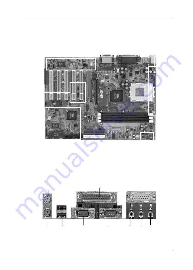
1-3 Mainboard Layout
PS/2 Mouse
PS/2 Keyboard
Printer Port
Game Port
USB 1/2 COM1
COM2 Line-out Line-in MIC
CN2,CN3,CN4B
JP5,JP6,FAN1
JP21
CN6
CN1,CN5,IR1,JP1,JP20,FAN2
SW1
Страница 1: ...f the FCC Rules Operation is subject to the following two conditions 1 This device may not cause harmful interference 2 This device must accept any interference received including interference that ma...
Страница 2: ...difications to this unit not expressly approved by the party responsible for compliance could void the user s authority to operate this equipment Canadian Department of Communications Statement This d...
Страница 3: ...eripherals 20 3 5 Power Management Setup 22 3 6 PnP PCI Configuration 25 3 7 PC Health Status 26 3 8 Frequency Voltage Control 26 3 9 Load Fail Safe Defaults 27 3 10 Load Optimized Defaults 27 3 11 Su...
Страница 4: ...e floppy LS120 CD ROM HDD IDE SCSI ZIP ATAPI etc Includes Trend ChipAway Virus protection for virus free boot and virus free operating system Embedded Ultra DMA 100 PCI IDE controller Supports two ID...
Страница 5: ...ckage Contents This product comes with the following components One mainboard One 40 pin 80 wire UDMA 100 IDE connector ribbon cable Figure 1 1 Color coded connection Blue to mainboard Gray to Master...
Страница 6: ...3 Introduction 1 3 Mainboard Layout PS 2 Mouse PS 2Keyboard Printer Port GamePort USB 1 2 COM1 COM2 Line out Line in MIC CN2 CN3 CN4B JP5 JP6 FAN1 JP21 CN6 CN1 CN5 IR1 JP1 JP20 FAN2 SW1...
Страница 7: ...er Indicator LED Connector 7 System Reset Switch Connector 7 Speaker Connector 7 Green Switch Connector 7 IDE Activity LED Connector 7 CN2 CD ROM Audio in 8 CN3 Auxiliary Audio in 8 CN4B Bass Center a...
Страница 8: ...dicate Pin 1 of the CPU 2 Pull up the lever of Socket 462 so that it is perpendicular with the surface of the mainboard Gently insert the CPU with Pin 1 at the same corner of Socket 462 that contains...
Страница 9: ...T button on the Windows 95 task bar Select Shut Down The Computer and the system turns off The message It is now safe to turn off your computer will not be shown when using this function Power On By M...
Страница 10: ...s the system s power status It is important to pay attention to the correct cables and pin orientation i e not to reverse the order of these two connectors C Green Switch LED Connector Some ATX cases...
Страница 11: ...under Wake Up Events in the BIOS s Power On Management screen You must also set this jumper s cap to pins 2 3 to use this function Power On By USB JP6 JP21 This board is able to be turned on by a USB...
Страница 12: ...is board contains a USB Host controller and includes a root hub with two USB 0 1 ports a connector for optional USB Adaptor USB 2 3 IR Connector IR1 Select a UART Mode in BIOS s Integrated Peripherals...
Страница 13: ...If you only use one bank it does not matter which one you use and if you use two or more banks it does not matter which bank you install first DDR SDRAM Specifications DIMM type 2 5V Registered64 128...
Страница 14: ...y to enter the Award BIOS setup program The primary screen as shown in Figure 3 1 is a list of the menus and functions available in the setup program Select the desired item and press enter to make ch...
Страница 15: ...this timer HardDiskSetup Primary Secondary Master Slave This category identifies up to four IDE hard disk drives that have been installed in the computer This section does not show information on othe...
Страница 16: ...n i g n o r e t h i s s e t t i n g i f y o u a r e u s i n g a V G A m o n i t o r s i n c e V G A B I O S a u t o m a t i c a l l y c o n f i g u r e s t h i s s e t t i n g Halt Halt Halt Halt Hal...
Страница 17: ...p e c i f i c v i r u s e s b u t r a t h e r d e t e c t s p a t t e r n s f o u n d i n e v e r y v i r u s e l i m i n a t i n g t h e n e e d t o p e r f o r m p e r i o d i c a l v e r s i o n u...
Страница 18: ...pletes BIOS will search these drives for an operating system SwapFloppyDrive Enabling this function will swap the floppy drive assignment so that drive A will function as drive B and drive B will func...
Страница 19: ...e Section 3 11 for password setting information When the Security Option is set to System a password must be entered to boot the system or enter the BIOS setup program When the Security Option is set...
Страница 20: ...mined by the mainboard manufacturer and should not be changed unless you are absolutely sure of what you are doing Explanation of the DRAM timing and chipset features setup is lengthy highly technical...
Страница 21: ...states PCIDelayTransaction The chipset has an embedded 32 bit posted write buffer to support delay transactions cycles Select Enabled to support compliance with PCI specification version 2 1 D Memory...
Страница 22: ...ory area a system error may occur G Flash BIOS Protection The mainboard manufacturer developed BIOS protection technology that protects the System BIOS from accidental corruption by unauthorized users...
Страница 23: ...g u r e 3 5 I n t e g r a t e d P e r i p h e r a l s S c r e e n F i g u r e 3 5 I n t e g r a t e d P e r i p h e r a l s S c r e e n F i g u r e 3 5 I n t e g r a t e d P e r i p h e r a l s S c r...
Страница 24: ...available modes D Init Display First This function allows user to choose between AGP slot or PCI slot to initialize Display first E OnChip USB Enable the on board Universal Serial Bus USB controller i...
Страница 25: ...to save electricity when it is not in use by entering increasingly deep power saving modes as shown by the diagram below Item Help Menu Level CMOS Setup Utility Copyright C 1984 2001 Award Software P...
Страница 26: ...ted Blank This function serves as both a screen saver and a power saver DPMS Supported Select this option if your video card supports the Display Power Management Signaling DPMS standard i e you have...
Страница 27: ...wer On By Modem Lan When enabled a modem that receives a signal will wake up the system from soft off and green mode You should connect the modem to the COM port and turn on the resume event in green...
Страница 28: ...o Yes B Resources Controlled By When set to Manual the system BIOS will not refer to the ESCD for IRQ DMA information Instead it will refer to the items in the setup menu for assigning IRQ DMA When se...
Страница 29: ...t a t u s S c r e e n CMOS Setup Utility Copyright C 1984 2001 Award Software PC Health Status Move Enter Select PU PD Value F10 Save ESC Exit F1 General Help F5 Previous Values F6 Fail Safe Defaults...
Страница 30: ...Copyright C 1984 2001 Award Software Esc Quit F10 Save Exit Setup Select Item Load Fail Safe Defaults F i g u r e 3 1 0 L o a d F a i l S a f e D e f a u l t s S c r e e n F i g u r e 3 1 0 L o a d F...
Страница 31: ...d and supervisor password selected in BIOS Figure 3 1 The main purpose of separating user and supervisor is to allow only the supervisor to have control over the settings in BIOS The user on the other...
Страница 32: ...ave only one BIN file to aviod confussion FLASH MEMORY WRITER V 7 52C FLASH MEMORY WRITER V 7 52C FLASH MEMORY WRITER V 7 52C FLASH MEMORY WRITER V 7 52C FLASH MEMORY WRITER V 7 52C C Award Software 2...
Страница 33: ...S DS3D DirectMusic Aureal A3D and Creative EAX Environment Audio Extensions C3DX APIs 4 o r 6 o p t i o n a l c h a n n e l s p e a k e r a u d i o s u p p o r t f o r H o m e T h e a t e r e n v i r...
Страница 34: ...a r e c o n n e c t e d t o L i n e i n R e a r j a c k W h e n L i n e i n R e a r j a c k i s c o n n e c t e d t o o t h e r e x t e r n a l L i n e i n s o u r c e s p l e a s e D O N O T e n a b...