CHAINTECH 7NIL1 Скачать руководство пользователя страница 11

Chapter 2     


17 

activities such as pressing a key on the keyboard or moving the mouse will bring 
the system back to Full-On. Pushing the button while in Full-On mode for more 
than [

4 seconds

] will switch the system completely off. See Over-ride Power 

Button Operation diagram. 

2. 

P-LED

 (Power LED Connector): 

The power indicator LED shows the system's power status. It is important to pay 
attention to the correct cables and pin orientation. (i.e., not to reverse the order of 
these two connectors.) 

3. 

G-BTN/G-LED

 (Green Button Switch/LED Connector): 

Some ATX cases provide a Green button switch, which is used to put the system in 
Suspend mode. In Suspend mode, the power supply to the system is reduced to a 
trickle, the CPU clock is stopped, and the CPU core is in its minimum power state. 
The system is woken up whenever the keyboard or mouse is touched. The system 
resumes in different ways as defined by Power Management Setup screen in BIOS. 

4. 

RESET

 (System Reset Switch Connector): 

This connector should be connected to the reset switch on the front panel of the 
system case. The reset switch allows you to restart the system without turning the 
power off. 

5. 

SPEAKER

 (Speaker Connector): 

This 4-pin connector connects to the case-mounted speaker. 

6. 

HD-LED

 (IDE Activity LED Connector): 

The IDE activity LED lights up whenever the system reads/writes to the IDE 
devices. 

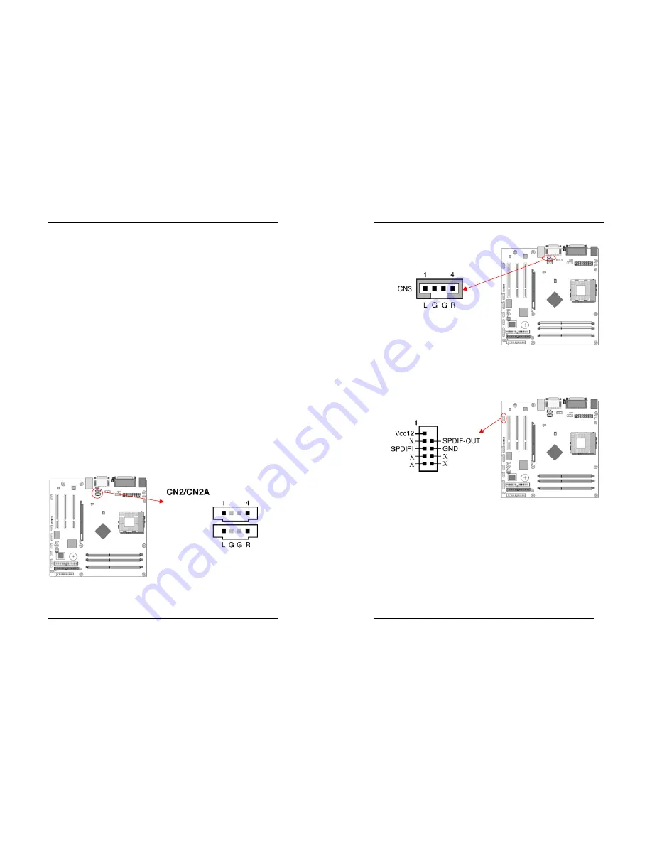
CN2/2A (CD-ROM Audio-in Connector): 


Use the audio cable enclosed with your CD-ROM disk drive to connect the 
CD-ROM drive onto your motherboard. This will enable your CD-ROM's audio 
function. 

Chapter 2   


18 

CN3 (Auxiliary Audio-in Connector): 


These connectors are for CD-Rom devices audio. It is for Auxiliary Audio-in Device, 
which will input the sounds sources into the motherboard. 
 

CN4C (SPIDIF KIT Connector) 


This connector must be connected to a 

SPDIF bracket

. This will allow you to use 

the SPDIF option. 

Содержание 7NIL1

Страница 1: ...tal device that complies with 47 CFR Parts 2 and 15 of the FCC Rules Operation is subject to the following two conditions 1 This device may not cause harmful interference 2 This device must accept any...

Страница 2: ...s document is subject to change without notice and does not represent a commitment on the part of the vendor No warranty or representation either expressed or implied is made with respect to the quali...

Страница 3: ...USB ports EHCI UHCI v1 1 compliant with over current protection Optional USB adapter for additional USB2 0 1 1 ports On board Super I O Controller ITE 8712 LPC I O with system monitors hardware Two U...

Страница 4: ...Chapter 1 3 1 3 7NIL1 Motherboard Diagram Chapter 1 4 1 4 7NIL1 Motherboard Layout...

Страница 5: ...e CPU to push itself into place Do not apply extra pressure as doing so may result in damaging your CPU Snap the lever back into place Installing an AMD approved heat sink with cooling fan is necessar...

Страница 6: ...onfiguration This motherboards provides 3 184pin Double Data Rate DDR Dual Inline Memory Modules DIMM slots Which supports PC 1600 DDR200 PC2100 DDR266 PC2700 DDR333 and PC3200 DDR400 DDR SDRAM module...

Страница 7: ...m including the power supply the keyboard and the various controllers on the front panel of the system case The power supply connector is the last connection to be made while installing a motherboard...

Страница 8: ...the poly fuse will return to its normal state Then the keyboard or USB connector can function properly again Unlike conventional fuses the poly fuse does not have to be replaced relieving the user was...

Страница 9: ...nd then press Enter to continue 5 Set the system configuration in the Standard CMOS Setup menu Pin Definition 1 2 Normal default 2 3 Clear CMOS Data Chapter 2 14 JP5 Keyboard Power On Function Jumper...

Страница 10: ...s cap setups up the CPU Ext Clock Frequency 1 2 The default value is 133 166 MHz The will allow the CPU s Ext Frequency and memory frequency to be adjusted through the BIOS 2 3 Set 100 MHz at CPU Ext...

Страница 11: ...ouse is touched The system resumes in different ways as defined by Power Management Setup screen in BIOS 4 RESET System Reset Switch Connector This connector should be connected to the reset switch on...

Страница 12: ...es WOL capability to the motherboard CN5A WOM Wake on Modem Connector The Wake Up On Modem selection in BIOS s Power Management Setup Menu must be enabled to use this function This header is used to c...

Страница 13: ...tains a USB Host controller and includes a root hub connector for optional USB Adaptor USB 2 3 and 4 5 Chapter 2 22 CN24 Front Audio Connector This connector give you the option of a front panel audio...

Страница 14: ...can retain the setup information even when the power is turned off To enter the Phoenix Award BIOS setup program press the Delete key when you Power on or reboot the computer system The primary screen...

Страница 15: ...s called POST Power On Self Test This function stops the computer if BIOS detects a hardware error You can tell BIOS to halt on all errors no errors or not to halt on specific errors Chapter 3 26 3 2...

Страница 16: ...essed and held down 3 Typematic Delay Msec The typematic delay sets how long after you press a key that a character begins repeating Security Option The Supervisor and or User Password functions shown...

Страница 17: ...ows Optimal Select this option will let the system automatically detect its performance Aggressive Select this option for a better system performance It increases a bit of the system performance Memor...

Страница 18: ...rmation on setting peripheral devices By choosing the Integrated Peripherals option from the CMOS Setup Utility menu Figure 3 1 the screen below is displayed This sample screen contains the manufactur...

Страница 19: ...able options are 3F8 IRQ4 2E8 IRQ3 3E8 IRQ4 2F8 IRQ3 Disabled and Auto 3 UART Mode Select This function allows you to select an operating mode for the second serial port Available options are Normal I...

Страница 20: ...buffer and the monitor s electron gun turns off This function requires a monitor with Green features in order to take advantage of the power saving function If you enable this function and do not hav...

Страница 21: ...from the CMOS Setup Utility menu Figure 3 1 the screen below is displayed This screen contains the manufacturer s default values for the motherboard Figure 3 7 PNP PCI Configurations Reset Configurati...

Страница 22: ...quency Voltage Control By choosing the Frequency Voltage Control option from the CMOS Setup Utility menu Figure 3 1 the screen below is displayed This sample screen contains the manufacturer s default...

Страница 23: ...et to Setup a password is required to enter BIOS and change BIOS settings When the Security Option function is set to System a password is required to enter both BIOS and the computer s operating syst...

Страница 24: ...up 1 Please select Nvidia Driver Package to begin installation 2 Please click NEXT to start installation Chapter 4 44 3 Please click OK to continue 4 Please click NEXT to continue 5 If you want to ins...

Страница 25: ...es I want to restart my computer now then Please Click OK to restart you computer If you do not want to restart your computer select No I will restart my computer later then click OK to continue Chapt...

Страница 26: ...e install the C Media Audio driver 4 Please click Next to continue install the C Media Audio driver Chapter 4 48 5 Please click Next to continue install the C Media Audio driver 6 Please click Next to...

Страница 27: ...ontinue 4 3 USB 2 0 Driver Setup By Choosing USB 2 0 Driver from the main menu it will provide the informations that you require to install the USB 2 0 Drive USB 2 0 only support Windows 2000 XP opera...

Страница 28: ...y diskette has only one BIN file to avoid confusion AwardBIOS Flash Utility V X XX C Phoenix Technologies Ltd All Right Reserved For XXXX XXXXXX XXXXXXXXXX X DATE XX XX 2002 Flash Type XXXXXX XXXXXXXX...

Отзывы: