7
Domestic Hot Water Mode
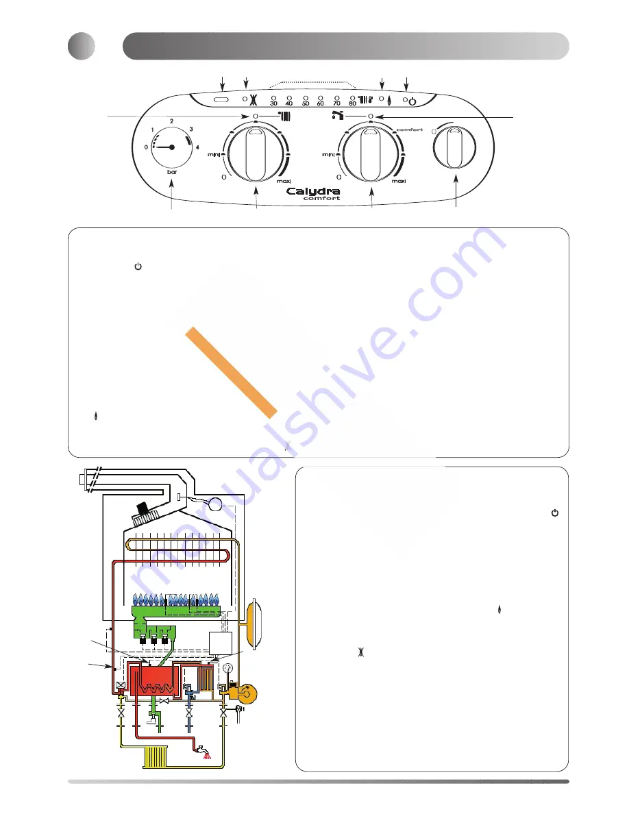
In order to supply hot water, the main switch 23 (Fig.5) must
be in the ON position I This will be confirmed by the green
indicator light
27 (fig. 5). Turn the D.H.W. temperature
adjustment knob 24 clockwise to establish the green D.H.W.
indicator 32 (Fig.5).
The hot water temperature in the mini cylinder can be
adjusted between 40 and 60°C using the control knob 24
(Fig.5).
When a tap or shower is turned on, the flow of mains water,
above 2 l/min, will activate the 3 way valve 17
(Fig.2) to move to the D.H.W. position. The pump will now
circulate primary water heated by the main heat exchanger
through the secondary heat exchanger.
The first stage solenoid a (Fig.6) and the safety solenoid c
(Fig.6) open together to allow gas to the burner. The ignition
sequence begins and a continuous high speed spark ignites
the gas. As soon as a flame is detected the orange indicator
bulb
28 (Fig.5) will light and the second stage solenoid b
(Fig.6) opens to allow the full gas rate. If a flame is not
detected, after 8 seconds, the security solenoid closes and
shuts off the gas. The red lockout indicator bulb
29
(Fig.5) will show. Over 2 l/min, the D.H.W. temperature is
controlled by the D.H.W. control thermistor d (Fig.6) and the
heating control thermistor e (Fig.6), but dependant upon the
position of the D.H.W. temperature adjustment knob 24
(Fig.5). This system anticipates the changes of temperature
in the secondary heat exchanger and ensures accurate
temperature regulation.
When the tap is closed the burner is extinguished and the
pump stops. (unless the TSS® thermistor is calling for heat,
in which case the burner will remain on at a low rate and the
pump will continue running until the mini cylinder thermistor is
satisfied). The boiler will now stay in the hot water mode for
30 seconds to be ready for a subsequent draw off
Priority is given to a demand for hot water. This will interrupt
the central heating for the duration of hot water delivery or
recovery of the mini cylinder.
When the boiler has been in standby in hot water mode for
some time or when drawing D.H.W. at flow rates of less than
2 l/min the temperature in the mini cylinder will eventually
decrease and the TSS® control thermistor f (Fig.6) will call for
heat, Causing the pump and burner to operate, until the
TSS® thermistor is satisfied.
5
Fig.5
Fig. 6
Central Heating Mode
To be able to supply heating, the main switch 23 (Fig.5) must be in
the I position. This will be confirmed by the green indicator light
27 (Fig.5). Turn the temperature control knob 25 clockwise to
establish the green heating indicator 33 (Fig.5).
When there is a demand for heating (either from the room
thermostat or the clock) and the boiler temperature control is
calling for heat. The pump starts allowing the ignition sequence to
begin. The first stage solenoid a (Fig.6) and safety solenoid c (Fig.
6) open together to allow gas to the burner. The ignition sequence
begins and a continuous high speed spark ignites the gas. As soon
as a flame is detected the orange indicator bulb
28 (Fig 5) will
light. After 45 seconds the second stage solenoid b (Fig 6) opens
to allow the full gas rate. If a flame is not detected, after 8 seconds,
the security solenoid closes and shuts off the gas. The red lockout
indicator bulb
29 (fig. 5) will show.
The central heating flow temperature is controlled by the central
heating control thermistor e (Fig 6). The boiler has been designed
to minimise cycling and will not attempt to relight for at least 3
minutes after the boiler thermostat has been satisfied (it is possible
to reduce the time to 30 seconds if necessary). When the room
thermostat is satisfied the burner will switch off and the pump will
remain running for a further 4 minutes before it to stops.
NB : It is possible to override the 3 minute delay by pressing the
RESET button 30 (Fig 5).
a b c
d
e
I
reset
32
31
30
23
25
33
26
24
27
28
29
f
Operation


