Modular
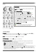
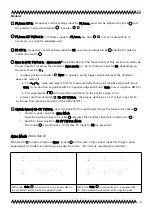
F2 fine tuning for frequency F2. Range is ≈ two semi notes.
FSK mode switch
see above ("Introduction")
/
Waveform selector
switches between (sinewave) or (triangle) oscillator waveform on
output socket
2
3
4
5 6
7
8 9
21
10
11
12
13 14
15 16
17
18 19
20
22
12
Objekt in Pfade:
4
.
FSK mode LED:
see above ("Introduction")
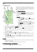
LED 'AM' for optical control of the amplitude modulation on output socket /
2
3
4
5 6
7
8 9
21
10
11
12
13 14 15 16 17
18 19
20
22
12
Objekt in Pfade:
4
:
-
●
blue: negative voltages on the oscillator's output
-
●
red: positive voltages on the oscillator's output
-
●
green: AM input voltage amount on "AM in" ; both for negative and positive voltages
In 'normal' audio-range oscillations (with poti "Bypass" turned cw) the color will become purple-
like as a mixture of red and blue; while the knob "Bypass" is turned ccw (and a signal is applied
on 'AM In' ) it will change into white and green, indicating the original signal proportion (from AM
input) on output /
2
3
4
5 6
7
8 9
21
10
11
12
13 14
15 16
17
18 19
20
22
12
Objekt in Pfade:
4
.
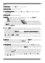
F1/com
F2
F1 Fine Tune
F2 Fine Tune
F1/com CV ins
F2 CV ins
+
Switch
"com"
Frequency
Control
VCO
FSK in
Switch "FSK"
F1
F2
Output
6
F1
F2
16
LO MID
HI
4
Σ
com
CV
F2
switch
changes the routing between the frequencies F1 and F2. In the upper position,
both frequencies F1 and F2 work independently and will be controlled separately by their respective
frequency knobs and/or CV inputs.
In the lower position, knob "F1/com" and sockets "F1/com CV" "F1/com CV 1V/Oct" affect
both F1 and F2. This coupling ensures that the ratio between F1 und F2 remains the same, and
tracks 1V/oct. using both frequencies within the FSK option. The ratio can only be changed by the
"F2" knob or the F2 CV inputs , .
Note that in this mode the frequency range is expanded and that for F2 four independent CV inputs
are now available.
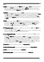
AM in level
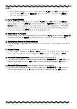
Input level control for the signal applied on socket 'AM In' for amplitude modulation
of the sinewave/triangle , provided on output /
2
3
4
5 6
7
8 9
21
10
11
12
13 14 15 16 17
18 19
20
22
12
Objekt in Pfade:
4
.
Note: This voltage is added to the DC voltage set by knob 'Gain' .
Gain adjustment
regulates a internal DC voltage for level control of the
/ oscillator signal:
In middle position, the oscillator signal is almost surpressed and can be used for ring modulation or
oscillator volume level control by a signal applied on 'AM In' ; the denter in middle position "0" may
be used as orientation.
This knob regulates an internal DC offset voltage of ca ±2,5V (added to the AM-input signal, which
level is adjustable by knob ); - a positive in clockwise and a negative voltage in ccw positions. In
ccw positions the / - phase is becoming inverted (See also "Examples" in chapter 2.2 "FSK").
In some applications the "Gain" knob may be used to alter the waveshape (by adding more or less
voltage to your input signal); e.g. if you feedback the / output
2
3
4
5 6
7
8 9
21
10
11
12
13 14
15 16
17
18 19
20
22
12
Objekt in Pfade:
4
to the AM-Input and
adjust and carefully)
4
2
3
4
5 6
7
8 9
21
10
11
12
13 14
15 16
17
18 19
20
22
12
Objekt in Pfade:
4
2
3
4
5 6
7
8 9
21
10
11
12
13 14
15 16
17
18 19
20
22
12
Objekt in Pfade:
4
2
3
4
5 6
7
8 9
21
10
11
12
13 14
15 16
17
18 19
20
22
12
Objekt in Pfade:
4
2
3
4
5 6
7
8 9
21
10
11
12
13 14
15 16
17
18 19
20
22
12
Objekt in Pfade:
4
2
3
4
5 6
7
8 9
21
10
11
12
13 14
15 16
17
18 19
20
22
12
Objekt in Pfade:
4
2
3
4
5 6
7
8 9
21
10
11
12
13 14
15 16
17
18 19
20
22
12
Objekt in Pfade:
4
2
3
4
5 6
7
8 9
21
10
11
12
13 14
15 16
17
18 19
20
22
12
Objekt in Pfade:
4
2
3
4
5 6
7
8 9
21
10
11
12
13 14
15 16
17
18 19
20
22
12
Objekt in Pfade:
4


