8 Technical indicators and testing methods
8.5 Performance characteristics test
104
USB2.0 interface
For connecting external memory
TF card interface
For connecting TF card for system software upgrade and backup data
LAN interface
RJ45 interface, TCP/IP interface, 10/100/1000M adaptive, for remote
analyzer operation
Power input connector
DC power socket (φ2.0mm) for connecting power adapter output plug
8.5 Performance characteristics test
Recommended test methods
………………………………………………………………………113
Performance test log sheet
Performance test auxiliary table
Recommended instruments for performance characteristics testing
8.5.1 Recommended testing method
8.5.1.1 Frequency range
a) Description of the test items
The frequency range indicates the range between the highest and lowest frequency signals that can be
correctly measured by the device.
Use a synthesis signal generator to generate the signal in the range of the upper and lower
measurement frequencies calibrated by the equipment to be tested, to check whether the frequency
measurement capability of the equipment is adequate.
b) Test equipment
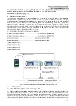
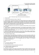
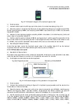
Synthetic Signal Generator ....................................... Recommend 1464/E8257D
Figure 8.1 Diagram of the frequency span test
c)
Test procedure
1) Connect the test equipment according to Fig. 8.1, the equipment to be tested and wait for the
synthesized signal generator sharing a common time base, and connect the synthesized signal
generator's low frequency output to the signal input of the equipment to be tested.
2) Set the low frequency generator output waveform of the synthesized signal generator as a sine
wave with the output frequency of 9kHz and output power of -
30dBm (10mV peak, 50Ω impedance).
3) Reset the device to be tested. Set the device to be tested as fixed frequency reception mode (FFM)
and set the frequency reference as external reference. Set the center frequency at 9 kHz and the
frequency width at 10 kHz. Use the peak frequency scale to read out the signal frequencies and record
the measurements in the 3943B Monitoring Receiver Functional Performance Test Auxiliary Table
(hereinafter referred to as the "Auxiliary Table") B.1.
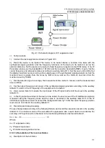
4) Connect the RF output of the synthesized signal generator to the RF input of the device to be tested,
and the device to be tested and the synthesized signal generator share a common time base. Set the
output frequency of the synthesized signal generator to 8Ghz, and the output power -30dBm.
Содержание 3943B
Страница 2: ...3943B Monitoring Receiver User s Manual Ceyear Technologies Co Ltd...
Страница 4: ......


