


CERWIN-VEGA! PROFESSIONAL
7
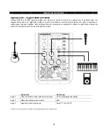
Quick Start
The steps below provide a quick reference on how to setup and use a single loudspeaker. A typical setup will follow the
same basic steps.
STEP 1
Make sure the loudspeaker is unplugged.
Be sure the master switch is to set to the ‘OFF’ position.
Turn the Volume to the lowest level (fully counter-clockwise)
Check that the loudspeaker voltage selector is set to the same voltage as the AC power outlet.
STEP 2
Place the loudspeaker in the ideal location. See the Loudspeaker Placement page for
recommended usage.
Connect the source audio equipment output to the loudspeaker input. Be sure the source
equipment is powered on and set to a normal output level.
STEP 3
Connect the power cord to the loudspeaker and AC power outlet.
Set the master power switch to the ‘ON’ position and verify the rear POWER LED indicator is
illuminated.
Slowly turn the volume clockwise until the sound output is at the desired level. If there is no
sound, check to make sure the source equipment is providing audio output.
NOTE(s)
When you are done using the loudspeaker, set the master power switch to ‘OFF’ before removing
any cables and turning off the source audio equipment.
Do not switch the loudspeaker voltage selector or MIC/LINE switch while the loudspeaker is
powered ‘ON’ and plugged into an AC power outlet.
Loudspeaker placement
Never point a microphone directly at a loudspeaker as this will result in extreme feedback (unwanted sound). Be
sure the loudspeaker is placed away from the front of the microphone or directly behind the microphone when
in a floor monitor position.
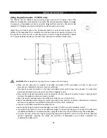
When used with turntables, carefully place the loudspeaker so that any vibrations do not interfere with the
turntable performance and functionality.
Avoid placing the loudspeaker in the corners or along the walls of a room. This will increase the low-frequency
sounds and the sound will result in a muddy and incoherent sound reproduction.
Avoid placing the speakers directly on a hollow stage. It is better to place the loudspeakers on tripod stands or a
sturdy table.
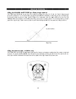
The loudspeaker should be placed two to four feet above the ear level of the audience since the human body
can absorb sound especially at high frequencies. This will make sure the entire audience can hear the sound
system with the best possible clarity.


