Cervis Warrior MU-6E-HVA Скачать руководство пользователя страница 16


Warrior


MU6E


U107.1.0 

10 

4.0 

Warrior MU6E Operation 

4.1 

System Startup 

Startup depends on the type of Warrior handheld transmitter that the MU6E receiver is 
associated to. Please reference the Warrior transmitter manual for Startup details. 
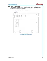
4.2 

Associate the Warrior MU6E with a Warrior Transmitter 

Cervis, Inc. pre-associates Warrior system receivers and transmitters before shipping the 
system. Depending on system configuration, the associate process is either locked or unlocked. 
(Most systems ship from Cervis, Inc. with association locked.) Each receiver will only 
communicate with the transmitter(s) that it is associated to. 

When necessary, other Warrior transmitters can be associated to the receiver

—either as 

additional spares or to replace damaged transmitters

—but first, the receiver association ability 

must be unlocked. 

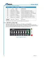
Unlock association on the MU6E in one of three different ways: 

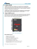
1.  Pressing the pushbutton (see Figure 2) unlocks association for five minutes. (Cervis, 

Inc. recommends this method because the receiver automatically returns to the locked 
state.) 

2.  With DIP switch 7 ON, an associated transmitter may unlock the receiver electronically. 

(

“Virtual Unlock” – see Warrior transmitter manual for instructions.) 

3.  Setting DIP switch 8 ON unlocks association and permits virtual unlock. Follow the table 

below. 

Table 5. MU6E DIP Switch 7-8 Configuration Status 

DIP 7 

DIP 8 

Status 

OFF 

OFF 

Association locked. Press MU6E pushbutton to enable association for five minutes. 

Default State 

ON 

OFF 

Association locked. Press MU6E pushbutton or use transmitter unlock procedure 
(virtual unlock) to enable association for five minutes. 

OFF 

ON 

Association unlocked. No additional action necessary. 

ON 

ON 

Association unlocked. No additional action necessary. 

Refer to your specific Warrior transmitter manual for association details. 

4.3 

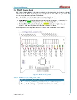
Additional Warrior Programming Features 

4.3.1  Horn/Light (Associate) Relay 

Each Warrior system has a Horn/Light relay. Cervis, Inc. recommends properly wiring this relay 
to some type of indicating device

—such as a horn or light—that is easily recognized when 

activated. When wired correctly, the operator will be alerted during the association process, and 
the receiver communicating can easily be identified. The Horn/Light relay can also be used to 
identify the following conditions. 

4.3.2  Tilt Fault Mode 

If the transmitter has a Tilt Fault Mode

—and it is tilted at least 60° from level—the Horn/Light 

relay begins pulsing once per second after three seconds. The operator then has three 
additional seconds to correct the tilt situation. 

Содержание Warrior MU-6E-HVA

Страница 1: ...2018 Cervis Inc MU6E Receiver Manual U107 1 0...

Страница 2: ...les limites de Sant Canada pour la population g n rale consulter le Code de s curit 6 disponible aupr s de Sant Canada site Web https www canada ca en health canada services environmental workplace he...

Страница 3: ...ming Features 10 4 3 1 Horn Light Associate Relay 10 4 3 2 Tilt Fault Mode 10 4 3 3 Low Battery Mode 11 4 3 4 Associate Mode is Unlocked 11 4 3 5 Association Nomination 11 5 0 MU6E Receiver Specificat...

Страница 4: ...Warrior MU6E U107 1 0 ii Table 4 MU6E Power Configurations 9 Table 5 MU6E DIP Switch 7 8 Configuration Status 10 Table 6 MU6E Receiver Specifications 12 Table 7 Warrior System Options 14...

Страница 5: ...cations technology Line of Sight aka Direct Line of Sight Term used to describe RF communication where the pathway between units is clear of physical obstacles such as walls earth and other obstructio...

Страница 6: ......

Страница 7: ...n that it is safe to do so Turn off the handheld remote transmitter and disconnect power from the machine unit receiver before attempting any maintenance This will prevent accidental operation of the...

Страница 8: ...tenna extension cables and integrated audible horn are also available 1 1 Warrior MU6E Receiver An MU6E can accept control commands from any transmitter that has the receiver identity ID stored in its...

Страница 9: ...maining six card slots can be populated with relay and or analog I O cards There are also eight diagnostic LEDs and other features described in the following sections 2 1 MU6E Main PCB The main PCB co...

Страница 10: ...Blinking Indicates messages sent to expansion card D8 Expansion RX Fast Blinking Indicates messages received from expansion card LED per Relay 4 Relay State Steady Lit Relay Active Each relay has its...

Страница 11: ...Inc 5 2 2 MU6E Power Card The MU6E power card accepts an input voltage that powers the unit This expansion card accepts 110VAC to 220VAC at 50Hz to 60Hz Line Fuse P N Little Fuse 0217002 H 250VAC 2A F...

Страница 12: ...hat resides on the main PCB Figure 2 Each relay has an LED indicator that illuminates when the relay is commanded ON This card has two diagnostic LEDs Table 2 describes the functions C1 and C2 Fuse P...

Страница 13: ...mpers two per channel must be configured so that two pins shown in the GREEN rectangle in Figure 6 are shorted together Current Mode The jumpers shown by the YELLOW rectangle in Figure 6 two per chann...

Страница 14: ...hen needed Mount the receiver away from any intense radio or electric disturbance sources Mount the receiver where there is enough room to make wiring harness terminations Make sure the mount is secur...

Страница 15: ...6E HVA High Voltage AC 110 to 220 Vrms 50 60 Hz In DC applications an external AC to DC converter must be used consult Cervis Inc Applications if needed 3 2 MU6E External Antenna MU6E units come with...

Страница 16: ...or transmitter manual for instructions 3 Setting DIP switch 8 ON unlocks association and permits virtual unlock Follow the table below Table 5 MU6E DIP Switch 7 8 Configuration Status DIP 7 DIP 8 Stat...

Страница 17: ...s soon as possible after the Low Battery Warning begins If the transmitter battery voltage drops to 2 0V the transmitter will shut down and cannot be used until fresh batteries are installed 4 3 4 Ass...

Страница 18: ...C Enclosure Dimensions mm 211 5 x 161 5 x 100 Inches 8 327 x 6 358 x 3 937 Durability NEMA 1 2 4 4X IP65 67 Mounting Mounting bracket Safety Circuit Designed to ISO 13849 Cat 3 PLD Contacts Common NO...

Страница 19: ...s on the torso Equipment containing the radio module was evaluated for RF exposure hazards by two approaches 1 Maximum Permissible Exposure MPE for mobile applications 2 Specific Absorption Rate SAR f...

Страница 20: ...alled 15104112 Two point mounting plate for receiver HH2S 9XL10 Spare transmitter HH2S 9XL10M Spare transmitter with vibratory feedback motor L152 Warrior 32 alternative button label sheet L154 Warrio...

Страница 21: ...Receiver Manual 2018 Cervis Inc 15 Visit our Web site at www cervisinc com 2018 Cervis Inc All rights reserved Content is subject to change without notice...

Отзывы: