


Remote Control Unit Manual
2019
Cervis, Inc.
3
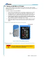
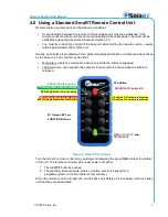
Two size AAA cell batteries power the SmaRT HH-x10, and it operates between 2.0VDC to
3.2VDC. Six visible status/diagnostic LEDs (see Figure 2) indicate transmit (
TX
) and receive
(
RX
) activity, communications errors (
ERR
), and low battery (
BAT
) warning. Two additional
LEDs
—
A1
and
A2
—offer custom-programmed auxiliary status indications.
Figure 2. Standard Ten-Button Example
Notice in Figure 2 that the ten function pushbuttons are unassigned to specific SmaRT base unit
outputs. This allows for maximum flexibility while programming to interface with the wide array of
available SmaRT base units. An example of a custom programmed HH-x10 is shown as the
center unit in Figure 1.
HH-x10 Remote Control Remote Options
The HH-x10 can be ordered with or without a belt clip. Table 1 lists the available models.
Table 1. HH-x10 Remote control Options
Model Name
Frequency
RF Power
Activation,
Deactivation
Belt
Clip
HH-9H10
900MHz
10mW
ON,OFF
NO
HH-9H10B
900MHz
10mW
ON,OFF
YES
HH-2H10
2.4GHz
100mW
ON,OFF
NO
HH-2H10B
2.4GHz
100mW
ON,OFF
YES
HH-9X10
900MHz
100mW
ON,OFF
NO
HH-9X10B
900MHz
100mW
ON,OFF
YES
OFF Button
ON Button
B1 through B10 are
FUNCTION Buttons
ASSOCIATE (button B1)
TX blinking Green when transmitting
RX blinking Amber when receiving
ERR blinking Red when error occurs
BAT blinking Amber when Low Battery
Protective Bumper
A1 (Auxiliary 1) Custom program use
A2 (Auxiliary 2) Custom program use
DISSOCIATE (button B2)


