Condensing Pool Heater
15
14/11/06
The boiler is fitted with automatic ignition and will
start when the gas cock is open, mains is connected
and the Pressure Switch is activated by the pool
Pump. (for greater detail about the internal controls
see the Maintenance section, Fault Diagnosis)
If the Heater fails to light the gas it will shutdown and
try again. It will repeat this a total of 5 times and then
lock out. This will show as the
Red
LED lit and
‘GAS’
on the display.
Press the Lock/Reset button to start another 5
attempts.
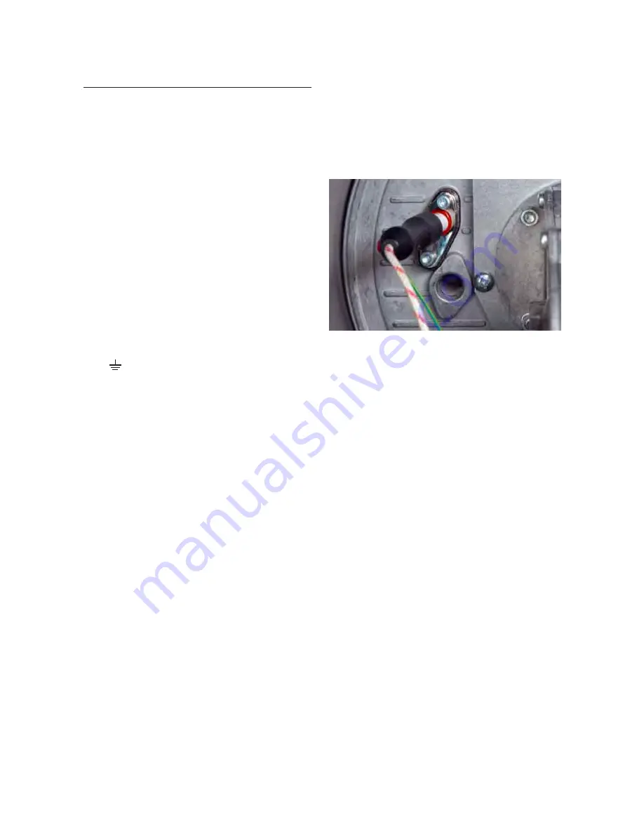
It is possible with the front door off to see when the
burner is lit through the sight glass.
(See Fig. 8.0)
After the burner has been lit for a few minutes the gas
rate and combustion should be checked, see the
Technical Data on Inside Cover
for details.
The Heater is factory set and should not require
adjustment. When the Heater has been running for at
least 10 minutes check all joints, gas and water, for
leaks, and correct where necessary.
Note:
The boiler is fitted with a syphon trap that in-
cludes a blocked drain detection device. This is to safe-
guard the boiler and help defer the effects from the
possible freezing of the condensate pipework in ex-
treme weather.
Should this happen the control will lockout and the dis-
play will show ‘
HI
’, as in “condensate level is high”.
See the Fault Finding section for more details.
This will have to be corrected before the Heater will
run.
The user should be made aware of this feature and,
that in the event of blocked or frozen condensate
pipework, the boiler will automatically stop function-
ing.
It will start again as soon as the blockage has cleared.
Finally, instruct the user on Heaters operation and
controls.
Fig. 8.0
Electrical Connections
WARNING: The appliance MUST be earthed.
All wiring for the Heater and system controls MUST
conform to I.E.E. Wiring Regulations, and work
should be tested using a suitable meter, for Earth
Continuity, Polarity, Short Circuit and Resistance to
Earth.
The Heater supply must be through a common
isolator, a double pole 3A fused isolating switch with
a contact separation of 3mm minimum on both
poles.
The cable used should be no less than 0.75mm
2
to
BS.6500 PVC, 3 core, and fixed ensuring the earth
connection is longer than the Live and Neutral.
Access to the Heater connections is made by the
removal of the Front Top Panel and the Electrical
Chassis cover, two screws.
The Heater’s internal wiring is shown in
Fig.11.0
.
Connections are as follows :-
4 Way Terminal
Supply Connection
Earth
N
Mains Neutral
SL
Switched Live
L
Permanent Live
A factory installed link has been fitted between SL
and L which should be removed if the Heater is to
have its own switched supply.
For systems using an external programmer, the
electrical wiring should follow the relevant control
manufacturer’s recommendations, with the switched
live from the controls returning to SL in the 4 way
push-fit connector.
It is possible to connect several Heaters together
using the Multiple Heater Kit. Details for the parts and
installation of this kit are given on Page 17.
Commissioning
General
The elimination of air from the heat exchanger is
essential to maximise the life of the Heater.
It is strongly recommended that the Heater is first
run with the
GAS OFF
until the air has been purged.
If air has not been released then there is a possiblity
of the Heater overheating and triggering one of its
safety thermostats.
Commissioning Procedure
The Heater Control is factory set to display in Fahr-
enheit and work to a maximum temperature of 90°F
(32°C). If a Centigrade display or higher, Spa tem-
perature 106°F ( 41°C) maximum is required, enter
Setup Mode.
(See Page 16)


