Radikal Gasser
Page 7
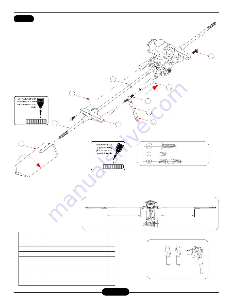
HEAD ASSEMBLY (HD VERSION)
Pushrod assembly (parts 2 through 4) is already assembled but check that the length is
actually 43mm (center to center). As the pushrods are built and installed they should be
checked for tightness. Press one ball link onto each double studded steel ball, making sure
that pressure is applied from the side of the ball link with circle mark. While holding one fly-
bar control arm, apply a small amount of slow cyanoacrylate glue and thread one end of the
double studded steel ball into each standoff. When it becomes difficult to turn with fingers,
apply slow CA to the threads and start screwing in the tapered control arm stand-off on
the other end of the ball. Slide and center the flybar through the head assembly. Care-
fully look at the flybar control arm assemblies from the previous step and notice
that when installed correctly, the securing set screw is on top. Insert one
M4x6x0.5 micro washer #CNLR1006 against each bearing then slide
the control arm halves onto each side, so that they match togeth-
er and the set screw remains on top. Insert one M3x12 but-
ton head socket screw to secure the opposite standoff.
Hold the tapered standoff using pliers while tight-
ening the screw as the rotor head
rotates clockwise.
Apply a small amount of cya-
noacrylate glue to the special
long thread ball.
All ball links are molded to be in-
stalled in only one direction. Look
carefully at the hole for the ball
as that side is 1mm larger .
Loosely tighten the M4x5 set screws into the round aluminum inserts aligned with the flat spots on the flybar. Tighten both set screws, one
at a time using Medium threadlock. Make a pencil mark 5mm past the threads on both ends of the flybar. Thread the flybar paddles onto the
flybar until the mark is reached and align the paddles parallel. Again using the ruler, rotate one paddle or the other to get equal distances while
remembering the leading edge of the paddles turn clockwise.
NOTICE SIZE OF HOLES ON BALL LINKS
THE SIDE WITH THE SMALLER HOLE
SHOULD FACE OUTWARDS
1
2
3
4
5
6
7
8
9
10
Make sure the distance on
both sides are equal
Make sure the distance on
both sides are equal
BAG 1
No.
Description
Qty
1
2
3
4
5
Part #
6
7
8
9
10
2
2
2
2
2
2
CNM4X5SS
CNM3X12BHCS
2
1
2
HI3176C
HI3176C
HI3176C
HW3173A
HI6179B
HI6145
HW6192
Flybar Paddles(
平衡翼
)
4mm Flybar 500mm(
平衡杆
)
M4x5 Socket Head Set Screw(
无头内六角螺丝
)
Pushrod Set(
拉杆
)
Flybar Arms(
Flybar Arms(
Flybar Arms(
平衡翼控制臂
)
球头双牙螺丝
)
Ball Link Set(
球头连接头
)
M3x12 Button Head Cap Screws(
圆头螺丝
)
CNLR1006
M4X6X0.5 Washer(
平面垫片
)
2
平衡翼控制臂
)
CNM3X12BHCS
CNM4X5SS
CA
HW3176C
Содержание Radikal G20
Страница 43: ...Radikal Gasser Page 43 PERSONAL BUILD NOTES ...


