background image

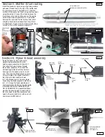
Section 3: Assembling the servo tray

Insert and attach the lower throttle servo on the left side (3.1) with the output “horn” fac-

ing the front of the servo tray. Install the upper collective servo above the throttle servo 

with the output facing the back (3.2). Attach the aileron servo (3.2) to the middle of the 

top portion of the servo tray with the horn facing forward. Attach the elevator servo to 

the left of the aileron servo horn facing rearward (3.2). Attach the power switch (3.3) to 

the switch plate provided on the right hand side of the servo frame. Slide the gyro in 

place (3.4). If possible, expose the gyro’s manual controls for future easy adjustment. 

Attach the servo frame assembly to the main frame assembly forward section (3.5 - 3.6) 

using provided hardware. Attach the rear rudder servo mount to the right hand aft sec-

tion of the upper side frame with the output facing rearward (3.7). Completed section 

(3.8) depicted.

3.1

3.2

3.3

3.4

3.5

3.6

3.7

3.8

Section 4: Fuel tank 

& fittings

Assemble the fuel stopper (found in 

the bag with the upper frames) (4.1) 

by bending the longer aluminum tube 

(connects to muffler nipple) so it will end 

at the top inside the fuel tank. Align the 

short straight aluminum tube level to the 

engine carburetor fuel intake. Secure 

with M3x18 screw supplied in clutch/fan 

package and tie wrap (4.2 & 4.3)

4.1

4.2

4.3

Front

install 

servos with 

M2.5x12 

self tapping 

screws

Screws for 

switch are 

provided 

with switch 

in radio 

system

Use thread lock

M3x6 washer 

head screws (2)

3x12 self tapping 

screws (2)

M3x25 socket head 

cap screws (2)

M3 locknut (2)

Fuel fitting set

assembled

6

Short straight tube

(sends fuel to engine)

Long curved 

tube (from 

muffler nipple)

Aileron servo

Elevator servo

Throttle 

servo

Collective 

pitch servo

Fuel line

fuel tank 

pickup  

“clunk”

M3x18 self 

tapping screw

Tie wrap

Содержание Hawk Pro

Страница 1: ...CIFICATIONS Main Rotor Diameter 49 5 in Tail Rotor Diameter 9 3 in Overall Length 46 in Height 16 2 in Engine 32 40 Ball Bearings 47 Century Helicopter Products Designed and Developed in USA 1st Edition April 2005 All rights reserved ...

Страница 2: ...packing of each bag Warranty Your new equipment is warranted to the original purchaser against manufacturer defects in material and workmanship for 30 days from the date of purchase During this period Century Helicopter Products will repair or replace at our discretion any component that is found to be factory defective at no cost to the purchaser This warranty is limited to the original purchaser...

Страница 3: ...ch Gauge with Paddle Gauge Part CN2034A 150 Curve Tip Ball link Pliers Part CN2052 Main Blade Balancer Part CN2054P Glow Plug Wrench Purple Part CN2055 Ball Link Sizing Tool Part CN2070 Universal Flybar Lock Part CN2155 Piston Locking Tool Part CN2219 Ball Link Easy Driver Part CN2255 Control Rod Guage Part CNWI26555 5 5mm Nut Driver Part CNWI26570 7 0mm Nut Driver Screwdrivers Slotted and Phillip...

Страница 4: ...apping screw 1 fuel cap 5 inches fuel tubing 1 5x13 flat washer 1 between cooling fan and engine nut 9x14 flat washer 1 replaces thrust washer on engine 3x16 socket head cap screws 4 3x8 self tapping screws 2 3x12 self tapping screw 2 3x6 washer head screws 2 Hardware Pushrods 1 foot fuel tubing 1 Pushrods 5 4x30 Socket head cap screws 2 main blade bolts M4 locknut 2 2 5x12 self tapping screws 20 se...

Страница 5: ...engine mount in the lower side frame assembly 2 1 After the engine is installed combine the upper and lower side frame sections 2 2 Before bolting attach the fan shroud securely to the frame assembly slightly overlapping the fan shroud portion of the upper side frames 2 3 Use hardware provided to finish assembling the frames 2 4 2 5 Install the canopy mounting hardware 2 6 2 7 by first threading one...

Страница 6: ... the right hand aft sec tion of the upper side frame with the output facing rearward 3 7 Completed section 3 8 depicted 3 1 3 2 3 3 3 4 3 5 3 6 3 7 3 8 Section 4 Fuel tank fittings Assemble the fuel stopper found in the bag with the upper frames 4 1 by bending the longer aluminum tube connects to muffler nipple so it will end at the top inside the fuel tank Align the short straight aluminum tube lev...

Страница 7: ...o ball bearings into the seesaw cups on each end Then slide the M3x6 plastic spacers on to each side of the flybar Next slide the 2 flybar control arms as shown 6 1 Use thread lock on the set screws connecting the flybar weights to the flybar 6 2 6 3 Align the flybar paddles and control arms level to the seesaw assembly LEADING EDGE OF PADDLES MUST GO CLOCKWISE The assembled flybar must be the same leng...

Страница 8: ...ue M3x30 socket head cap screws 2 M3 Locknut 2 M3x16 socket head cap screws 2 M3 Locknut 2 Place a small dab of gear grease synthetic hydrogen grease between the two plastic gears Section 8 Tail boom drive system The tail section 8 1 is completely assembled and only requires to be attached to the main frame use a small amount of gear grease inside the tail gearbox Slide the tail boom into the aft ...

Страница 9: ...en the fin clamp and the fin Screws are provided for mounting the verti cal fin in the package containing the fins 9 3 9 1 9 2 9 4 Section 11 Throttle Collective linkage Pushrod measurements include ball links from plastic end to plastic end Before any pushrod adjustments are made center both sticks and all servos on the transmitter Attach the 103mm throttle control rod to the throttle servo and the t...

Страница 10: ...am protection recommended by your radio manufacturer and secure to the top of the battery receiver platform at the lower front of the servo tray use 64 rubber bands Pushrod measurements include ball links from plastic end to plastic end Adjust the two aileron control rods to 158mm and attach the two balls on the aileron servo wheel and to the two aileron bellcranks Adjust the eleva tor control rod...

Страница 11: ...h to the canopy 17 6 Then mount the canopy on the helicopter 17 5 17 6 Mark location Section 16 Antenna routing Thread the small clear tube into the guides located on the right bottom side of the struts on the side opposite the muffler Insert the receiver antenna into the tube and secure to the rear area of the tail boom or one of the boom support struts It is recommend ed that you use a small rubb...

Страница 12: ...CNBB1030 2 Seesaw pivot shaft set HW3161A Upper Side Frame Interior Main shaft HW3053A Ball bearing 10x19 CNBB1019 Counter gear HI3040 Main shaft collar HW3054A Main gear HI3056 Autorotation bearing set HW3050 inside main gear Ball bearing 8x19 CNBB1980 Alloy drive gear HW3045 Torque tube coupler HI3154 Ball bearing 5x13 CNBB1350 Tail drive output shaft spacer HW3059A Tail rotor output gear HW3057...

Страница 13: ...0730 ball bearing Collective pitch lever set HW3024 Elevator lever set HI3032C Hex start adapter CN0402 Start shaft set with spring CN2226 Start shaft bearing blocks HI3007 uses 2 CNBB1150 5x11 ball bearings Bell mixer arm M3 washer 2 M3 spacer 2 M3x7 ball bearing 2 CNBB0730 M3x16 Socket cap screw 2 Bell mixer arm HI3189A M3x7 ball bearing 2 CNBB0730 Short ball CNLR1011 Long ball CNLR1012 ...

Страница 14: ... lever set HI3032B M3x7 ball bearing 4 CNBB0730 2 per bellcrank Collective lever set HW3024 Collective lever set HW3024 Aileron bell crank set HI3031B M6x10 ball bearing 2 CNBB1060 Swashplate set HI3146B Collective lever set HW3024 M3x10 socket head cap screw 4 2 on each side Collective pitch lever 14 ...

Страница 15: ...4 set screw Spring between collar and M5x10 flat washer M5x10 flat washer between spring and lower bearing block Hardened start shaft with spring HW3005A Hex start adapter CN0402 M3x4 set screw using thread lock Flybar assembly M3x7 ball bearing 2 CNBB0730 Flybar con trol arm set HI3176 M3x4 Set screw Flybar paddle set HI3179 Flybar HW3173 M4x5 Set screw 15 ...

Страница 16: ...de frame set HW3112C Engine mount HW3017 Lower Side Frames Tail drive shaft set HW3063TS Tail gear box left right HI3078 Ball bearing 2 5x13 CNBB1350 Tail gear set HI3075 Tail gear box input shaft HW3070A Tail output spacer HW3074 Ball bearing 5x11 CNBB1150 Ball bearing 5x11 CNBB1150 Tail output shaft HW3073 Tail rotor hub HW3098 16 ...

Страница 17: ...Tail Blade Grips Tail Section Exterior M2 hex nut 4 M2x10 phillips machine screw 4 M3x10 Ball bearing 2 CNBB1030 M3x10 socket head cap screw 2 M3x4 set screw Tail pitch ball link set HI3089 Tail pitch plate assembly brass slider HI3087A Tail pitch plate assembly HI3087A Ball bearing M6x10 2 CNBB1060 Tail pitch plate Tail pitch ball link set HI3089 Tail pitch lever Tail pitch lever set HI3102A M3x1...

Страница 18: ...ade Parts Accessories CN0427 Hex start wand with one way bearing CN2005 Main Blade Transport Supports CN2007A Trainer Pod 30 50 w 4 Legs CN2015 Hardened Tip Hex Wrench Set 1 5mm 2 0mm 2 5mm 3 0mm tips CN2016 4 8V Battery Monitor Alarm CN2018 PG 2000II Dual Rate Remote Gain Piezo Gyro CN2022 Single rate micro piezo gyro CN2046 Basic Heli Setup Tool Kit pitch gauge blade balancer pliers CN2052 Accur...

Страница 19: ...Clutch bell Clutch shoe Engine mount 30 size Cooling fan shroud Collective pitch lever set Aileron bellcrank set Elevator lever set Adjustable cyclic link set Counter drive gear Primary drive shaft Alloy drive gear Autorotation bearing set Main shaft Main shaft collar Main gear Tail transmission bevel gear Tail drive primary shaft Tail boom pipe Tail drive shaft set Tail control rod Tail fin set Ta...

Страница 20: ...nt mounts Canopy Decal set Windshield Fuel tank parts set Ball link set HI3130B HI3131M HI3133A HI3138A HI3145 Swashplate set Washout unit Radius links Main rotor hub Seesaw pivot lever Seesaw lever set Seesaw offset plate Seesaw tie bars Seesaw Bearing cups Special ball M3x6 Washout pins Flybar Flybar control arm set Flybar paddle set Feathering shaft set Dampening rubbers Main rotor blade grips ...

Страница 21: ...set Century Hawk Pro Upgrades Transfers all loading from the regular radial bearings to the thrust bearing Main Shaft Thrust Bearing Kit CN2220A Thrust Bearing Kit O S Throttle Extension CN2153 Throttle extension Carbon Graphite Tail Boom Support Super high quality extremely light weight and ready to install dual tail boom support kit CN2128 Carbon Support CN2124 NG Antenna Neon Green CN2124 NY An...

Страница 22: ...form or by any means electronic mechanical photocopy ing recording or otherwise without the prior written permission of the publisher Century Helicopter Products CCPM Conversion The 6mm spindle takes the high G stresses of 3D better and the thrust bearings make for smoother pitch control at high rotor speeds CNC precision machined aluminum clutch bell with replaceable gear and lining Outstanding f...

Отзывы: