background image

Page 10

For technical questions, please call 1-888-866-5797.

Item 69269 


SAFETY

OPERA

TION

MAINTENANCE

SETUP

Operating Instructions

Read the ENTIRE IMPORTANT SAFETY INFORMATION section at the beginning of this 

manual including all text under subheadings therein before set up or use of this product.

Compressor Area Set Up

1.  Designate a work area that is clean and well-lit.  

The work area must not allow access by 

children or pets to prevent injury.

2.  Locate the Compressor on a flat level surface to 

ensure proper pump lubrication and to prevent 

damage to the unit.  Keep at least 12″ of space 

around the unit to allow air circulation.

3.  Route the power cord from the compressor 

to the grounded wall outlet, along a safe path 

without creating a tripping hazard or exposing 

the power cord to possible damage.
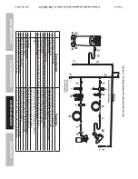
General Operation

1.  Close the Drain Valve.

2.  Close the in-line Shutoff Valve between 

the compressor and the air hose.

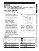
3.  Plug the Air Compressor Power Cord into 

a grounded 120 VAC electrical outlet.

4.  Turn the Power Switch ON.

5.  Allow the Air Compressor to build 

up pressure until it cycles off.

Note:

 At the beginning of the day’s first use of the 

Air Compressor, check for air leaks by applying soapy 

water to connections while the Air Compressor is 

pumping and after pressure cut-out.  Look for air bubbles.  

If air bubbles are present at connections, tighten 

connections.  Do not use the Air Compressor 

unless all connections are air tight, the extra air 

leaking out will cause the compressor to operate 

too often, increasing wear on the compressor.

Note:

 As long as the Power Switch is ON, the operation 

of the Air Compressor is automatic, controlled by an 

internal pressure switch.  The Compressor will turn on 

automatically when the air pressure drops to 85 PSI, 

and will turn off automatically when the 

air pressure reaches 100 PSI.   

WARNING! TO PREVENT SERIOUS 

INJURY AND DEATH FROM EXPLOSION:


Do not adjust the internal 

pressure switch.  

Any change to the 

automatic pressure levels may cause 

excess pressure to accumulate, 

causing a hazardous situation.

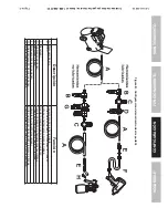
6.  Adjust the Air Compressor’s Pressure Regulator 

so that the air output is enough to properly 

power the tool, but the output will not exceed 

the tool’s maximum air pressure at any time.  

Turn the knob clockwise to increase the pressure 

and counter-clockwise to decrease pressure.  

Adjust the pressure gradually, while checking 

the air output gauge to set the pressure.

7.  Make sure the air tool’s throttle or switch is in the 

off position.  Connect the air tool to the air hose.

8.  Open the in-line Shutoff Valve.

9.  Use the air tool as needed.

10. After the job is complete, turn the Power Switch OFF.

11.  Unplug the Air Compressor.

12. Close the in-line Shutoff Valve.

13. Bleed air from the tool then disconnect the tool.

14. Turn the Drain Valve, at the bottom of the Tank, 

two turns to release any built-up moisture and the 

internal tank pressure.  Close the valve after moisture 

has drained out.  Do not remove the Drain Valve.

15. Clean, then store the Air Compressor indoors.

Содержание CentralPneumatic 69269

Страница 1: ......

Страница 2: ...ymbol It is used to alert you to potential personal injury hazards Obey all safety messages that follow this symbol to avoid possible injury or death Indicates a hazardous situation which if not avoid...

Страница 3: ...use this compressor while you are tired or under the influence of drugs alcohol or medication A moment of inattention while operating a compressor may result in serious personal injury b Use personal...

Страница 4: ...essure of 150 PSI or 150 of the maximum system pressure whichever is greater 14 USE OF AN EXTENSION CORD IS NOT RECOMMENDED If you choose to use an extension cord use the following guidelines TABLE A...

Страница 5: ...risk of electric shock The conductor with insulation having an outer surface that is green with or without yellow stripes is the equipment grounding conductor If repair or replacement of the electric...

Страница 6: ...section at the beginning of this manual including all text under subheadings therein before set up or use of this product TO PREVENT SERIOUS INJURY FROM ACCIDENTAL OPERATION Turn the Power Switch OFF...

Страница 7: ...er e Turn the Power Switch OFF f Unplug the Power Cord and remove the male coupler 3 Connect a regulator valve an inline shut off valve and a 1 4 NPT air hose to the Quick Coupler all sold separately...

Страница 8: ...Hose Connects air to tool B Filter Prevents dirt and condensation from damaging tool or work piece C Regulator Adjusts air pressure to tool D Lubricator optional For air tool lubrication E Coupler an...

Страница 9: ...bration reduction E Main Air Line 3 4 minimum recommended Distributes air to branch lines F Ball Valve To drain moisture from system G Branch Air Line 1 2 minimum recommended Brings air to point of us...

Страница 10: ...unless all connections are air tight the extra air leaking out will cause the compressor to operate too often increasing wear on the compressor Note As long as the Power Switch is ON the operation of...

Страница 11: ...automatically shuts off before reaching its normal cutoff pressure a Shut off all tools b Wait until the Compressor cools down about 10 minutes c If the unit does not start up again on its own press t...

Страница 12: ...qualified service technician Maintenance Schedule Following are general guidelines for maintenance checks of the Air Compressor Note The environment in which the compressor is used and the frequency...

Страница 13: ...r filters need cleaning replacing 2 Check Valve needs service 3 Compressor not large enough for job 4 Loose fittings 5 Hose or hose connections too narrow 6 High altitude reducing air output 1 Check i...

Страница 14: ...shown for illustration purposes only and are not available individually as replacement parts Part Description Qty 1 Motor 1 2 Crank 1 3 Screw 1 4 Bearing 608 2RS 1 5 Connecting Rod 1 6 Silica Gel Rin...

Страница 15: ...ON MAINTENANCE SETUP Assembly Diagram 3 6 5 2 6 2 1 4 3 1 6 1 5 7 5 8 4 8 2 6 2 4 2 7 2 5 2 8 4 6 4 7 5 3 5 4 5 5 5 9 6 0 4 2 3 7 9 5 1 2 3 3 5 3 5 6 3 2 4 8 2 1 1 0 1 1 1 3 1 7 1 8 1 6 4 3 4 5 4 4 3...

Страница 16: ...o the above limitation of exclusion may not apply to you THIS WARRANTY IS EXPRESSLY IN LIEU OF ALL OTHER WARRANTIES EXPRESS OR IMPLIED INCLUDING THE WARRANTIES OF MERCHANTABILITY AND FITNESS To take a...

Страница 17: ...nterior limitaci n de exclusi n no sea aplicable a usted ESTA GARANT A SUSTITUYE EXPRESAMENTE TODAS LAS DEM S GARANT AS EXPRESAS O IMPL CITAS INCLUIDAS LAS GARANT AS DE COMERCIABILIDAD Y ADECUACI N Pa...

Страница 18: ...7 SEGURIDAD FUNCIONAMIENTO MANTENIMIENTO CONFIGURACI N Diagrama de montaje 36 52 62 14 31 61 57 58 48 26 24 27 25 28 46 47 53 54 55 59 60 42 37 9 51 23 35 3 5 6 32 4 8 2 1 10 11 13 17 18 16 43 45 44 3...

Страница 19: ...e repuesto Pieza Descripci n 1 Motor 1 2 Cig e al 1 3 Tornillo 1 4 Cojinete 608 2RS 1 5 Varilla de acoplamiento 1 6 Anillo de gel de di xido de silicio 21 2 x 2 5 1 7 Aro de pist n 1 8 Almohadilla de...

Страница 20: ...ario limpiar reemplazar los filtros de aire 2 La v lvula de retenci n necesita mantenimiento t cnico 3 El compresor no es lo suficientemente grande para el trabajo 4 Acoples sueltos 5 La manguera o la...

Страница 21: ...rama de mantenimiento A continuaci n se indican las pautas generales para los controles de mantenimiento del compresor de aire Nota El ambiente en el que se utiliza el compresor y la frecuencia de uso...

Страница 22: ...imentaci n en la posici n APAGADO Luego tire del anillo de la v lvula de seguridad para liberar r pidamente la presi n de aire almacenada Sistema de apagado autom tico 1 Si el compresor se apaga autom...

Страница 23: ...corte por presi n Busque burbujas de aire Si nota la presencia de burbujas de aire en las conexiones aj stelas No utilice el compresor de aire a menos que todas las conexiones est n herm ticamente ce...

Страница 24: ...cundarias F V lvula esf rica Para drenar la humedad del sistema G L nea secundaria de aire se recomienda de 1 2 m nimo Transporta el aire hasta el punto de uso H Manguera de aire Conecta el aire a la...

Страница 25: ...ci n causen da os a la herramienta o pieza de trabajo C Regulador Regula la presi n de aire a la herramienta D Lubricador opcional Para la lubricaci n de herramientas neum ticas E Acoplador y tap n Pr...

Страница 26: ...sici n OFF APAGADO f Desenchufe el cable de suministro el ctrico y quite el acoplador macho 3 Conecte una v lvula reguladora una v lvula de cierre en l nea y una manguera de aire de 1 4 NPT al acoplad...

Страница 27: ...BRE SEGURIDAD que se encuentra al comienzo de este manual incluyendo todos los textos debajo de los subt tulos ADVERTENCIA PARA EVITAR LESIONES GRAVES CONSECUENCIA DE UN FUNCIONAMIENTO ACCIDENTAL Ante...

Страница 28: ...el conductor de conexi n a tierra del equipo puede generar un riesgo de sufrir descarga el ctrica El conductor de conexi n a tierra del equipo es el que posee un aislamiento cuya superficie exterior e...

Страница 29: ...OMIENDA EL USO DE UN CABLE DE EXTENSI N Si decide utilizar un cable de extensi n utilice las siguientes pautas TABLA A CALIBRE M NIMO RECOMENDADO PARA CABLES DE EXTENSI N 120 VOLTIOS AMPERIOS INDICADO...

Страница 30: ...lo que hace y use el sentido com n cuando utilice este equipo Cuando est cansado o bajo la influencia de drogas alcohol o medicamentos no utilice este compresor La m s breve falta de atenci n al oper...

Страница 31: ...bre potenciales riesgos de sufrir lesiones personales Para evitar posibles lesiones o la muerte acate todos los mensajes de seguridad que acompa an a esta se al PELIGRO Indica una situaci n peligrosa...

Страница 32: ......

Отзывы: