


Page 9
For technical questions, please call 1-800-444-3353.
SKU 44505
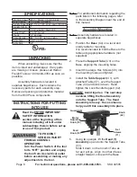
Thread in two Set Screws (11), into the
6.
side of the Head (1) and tighten.
Attach Knob (A2) to the (top) pulley
7.
Guard (A5) using Pan Head Screw (A3).
Adjust
8.
belt (a4)
tension:
Open the pulley Guard (A5) to expose
a.
the Belt.
Turn the Motor Adjusting Knob (10)
b.
counterclockwise to loosen Belt
Tension.
Push the Motor backward, tightening the
c.
Belt on the pulleys, and hold in place.
Turn the Motor Adjusting Knob
d.
clockwise to tighten the Belt in place.
Refer to the chart inside the Guard lid to
e.
select speed and belt locations.
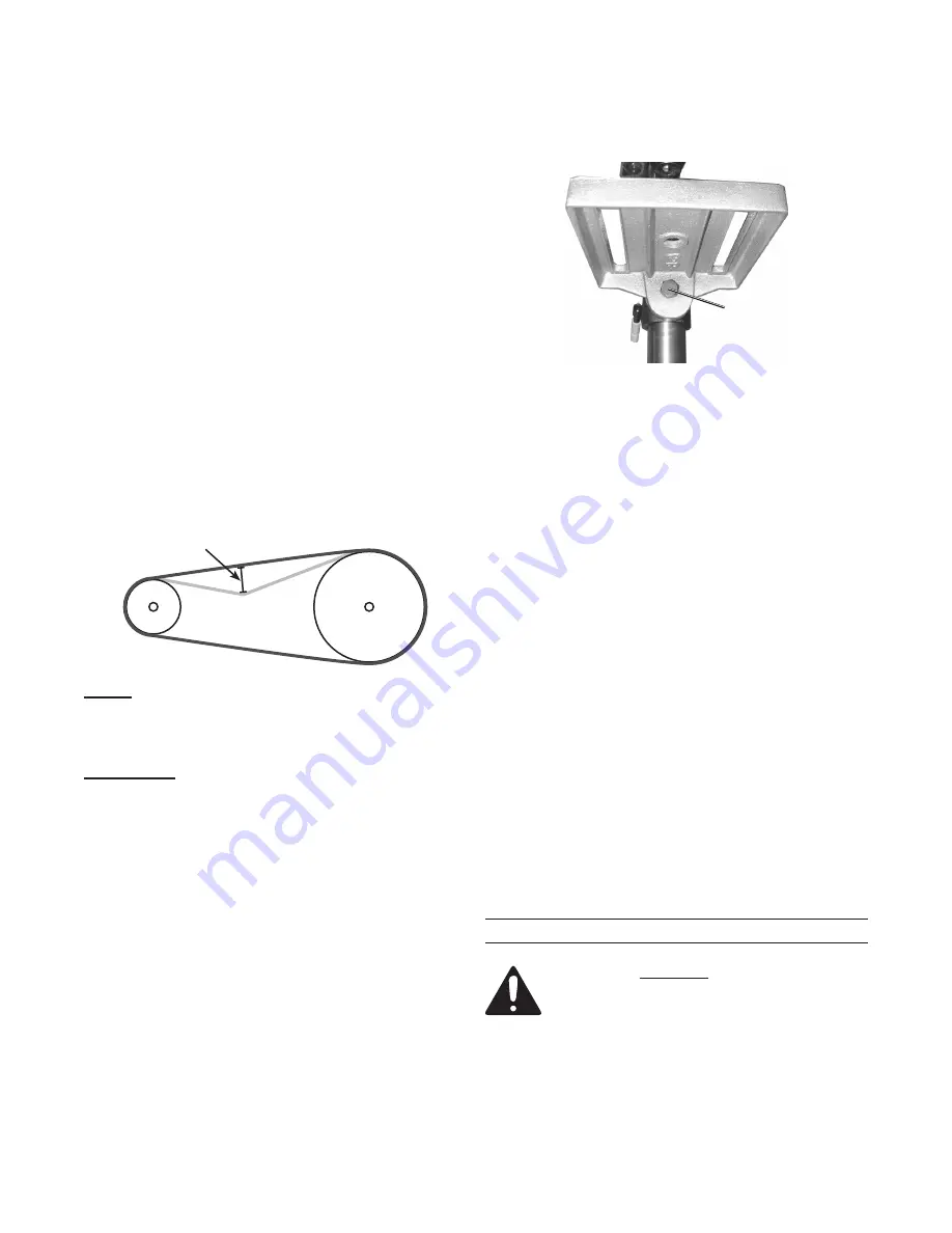
note:
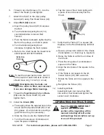
Deflection
Distance
To test the proper belt tension, push in
on the center of each belt at its center. It
should move only 1/2 inch (in or out).
cautiOn! Overtightening the belts can
cause the motor to bind, and not start.
it can also damage Motor bearings.
Thread the
9.
Feed knobs (12)
and
rods
(13)
onto the Pinion Shaft (14) and
tighten them.
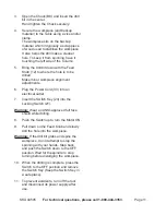
Install the
10.
chuck (b8)
:
Thoroughly clean the tapered hole in the
a.
Chuck and the Spindle Shaft (B7) of all
dirt, grease, oil, and protective coatings
(paint thinner may be necessary).
Slide the Chuck onto the Spindle Shaft.
b.
Turn the Chuck sleeve clockwise and
c.
open the jaws completely.
Tap the nose of the Chuck lightly with
d.
a piece of wood to securely set the
Chuck.
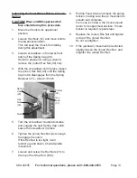
Screw (C6)
11. Verify that the Table (C7) is square (90
degrees) to the Head Assembly and drill
bit.
Secure a three inch drill bit in the Chuck
a.
(hand tighten, no chuck key is required).
Raise the Table to within four inches of
b.
the Chuck.
Place the long side of a combination
c.
square on the Table.
Align the short side of the square to the
d.
drill bit.
If the Table is not square to the bit,
e.
loosen Screw (C6) with a wrench.
Rotate the Table until it is square to the
f.
bit.
Retighten the Screw (C6).
g.
Install Light Bulb:
12.
Install light bulb (not more than 5W)
into socket, then install and tighten the
socket cover clockwise.
OPerating instructiOns
read the entire iMPOrtant
saFetY inFOrMatiOn
section at the beginning of this
manual including all text under
subheadings therein before set up
or use of this product.