background image

Page 15

SKU 95951

For technical questions, please call 1-800-444-3353.

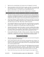
The LCD Display will count down the time remaining in the process. When the time 

5. 

reaches “0” the process will automatically stop.

Refilling the Automotive System with Oil and Refrigerant

Vehicle manufacturers design for and specify a specific amount of refrigerant for 

1. 

best operation of your vehicle A/C system. This amount is specified in weight. Too 

much or too little refrigerant will adversely effect the operation of the A/C system. 

Some newer vehicles will shut down the A/C system if too much refrigerant is in 

the system.
After recovery, check the amount of used oil separated from the automotive sys-

2. 

tem, and be sure there is at least 20 ml more new oil in the New Oil bottle than the 

amount removed. If there is not enough oil in the bottle, close the Oil Charge Valve 

(I-9) and add oil to the new oil bottle.
Check to be sure the HP and LP valves on the Control Panel are open.

3. 

Slowly open the Oil Charge Valve (I-9) allowing new oil to be sucked into the au-

4. 

tomotive A/C system. Do not open the valve all the way, rather, use it carefully to 

control the flow of oil. Allow oil to flow into the system until 10 ml more than the 

amount removed has been added back.

When sufficient oil has flowed back into system, close Oil Charge Valve.

5. 

Press the “Refilling” Key on the Control Panel. The machine will begin to replace 

6. 

refrigerant in the vehicle A/C system.  The Refilling Indicator light will be on.
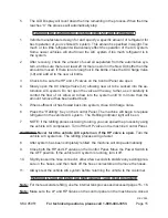
NOTE: If the refilling process is taking too long, you can speed the process by using 

7. 

the vehicle A/C compressor. Turn off the HP valve on the machine Control Panel.

WARning! never turn the vehicle A/C system on if the hp valve is open. 

Turn the 

vehicle A/C system on. The refilling process will go faster.
After system has been completely refilled, the machine will stop automatically.

8. 

Close both the HP and LP valves on the Control Panel. Move the Power Switch to 

9. 

the OFF position. If the vehicle A/C system is running, turn it off.
Slightly loosen the hose connector, allow a few seconds to stabilize any existing pres-

10. 

sure in the hoses, and then back off the hose connectors and remove the hoses.
Always test the vehicle A/C system before returning the vehicle to the customer.

11. 

Refilling Using an External Refrigerant Tank (Not Included)

note:

  For more accurate refilling, use the internal tank process as discussed pages 15 - 16.

note:

  Make sure the LP and HP Valves on the control panel on the machine are closed.

REV 09h

Содержание 95951

Страница 1: ...ls 3491 Mission Oaks Blvd Camarillo CA 93011 Visit our website at http www harborfreight com Read this material before using this product Failure to do so can result in serious injury Save this manual Copyright 2007 by Harbor Freight Tools All rights reserved No portion of this manual or any artwork contained herein may be reproduced in any shape or form without the express written consent of Harb...

Страница 2: ...y warnings and precautions assembly oper ating inspection maintenance and cleaning procedures parts list and assembly diagram Keep your invoice with this manual Write the invoice number on the inside of the front cover Write the product s serial number in the back of the manual near the assembly diagram or write month and year of purchase if product has no number Keep this manual and invoice in a ...

Страница 3: ...r the three wire grounded power cord and grounded power supply system Avoid body contact with grounded surfaces such as pipes radiators ranges 3 and refrigerators There is an increased risk of electric shock if your body is grounded Do not expose powered machines to rain or wet conditions 4 Water entering a powered machine will increase the risk of electric shock Do not abuse the Power Cord Never ...

Страница 4: ... use the machine for a purpose for which it is not intended Do not use the powered machine if the Power Switch does not turn it on or 2 off Any machine that cannot be controlled with the Power Switch is dangerous and must be replaced Disconnect the Power Cord Plug from the power source before making any 3 adjustments changing accessories or storing the machine Such preventive safety measures reduc...

Страница 5: ... sure you are prepared to begin work before turning on the machine Always keep the extension cord away from moving parts on the machine or 5 the vehicle People with pacemakers should consult their physician s before using this 6 product Electromagnetic fields in close proximity to a heart pacemaker could cause interference to or failure of the pacemaker In addition people with pacemakers should ad...

Страница 6: ...th parking 14 brakes locked and wheels chocked Never start the vehicle or operate the vehicle A C system if the hose is con 15 nected to the HP system and the HP Valve on the Control Panel is open WARNING The brass components of this product contain lead a chemical 16 known to the State of California to cause birth defects or other reproductive harm California Health Safety code 25249 5 et seq GRO...

Страница 7: ...a special 1 double insulation system which satisfies OSHA requirements and complies with the applicable standards of Underwriters Laboratories Inc the Canadian Standard Association and the National Electrical Code See Outlets for 2 Prong Plug Double insulated machines may be used in either of the 120 volt outlets shown in 2 the preceding illustration See Outlets for 2 Prong Plug Extension Cords Gr...

Страница 8: ... repaired by a qualified electri cian before using it Protect your extension cords from sharp objects excessive heat and damp or wet 8 areas RECOMMENDED MINIMUM WIRE GAUGE FOR EXTENSION CORDS 120 or 240 VOLT NAMEPLATE AMPERES at full load EXTENSION CORD LENGTH 25 Feet 50 Feet 75 Feet 100 Feet 150 Feet 0 2 0 18 18 18 18 16 2 1 3 4 18 18 18 16 14 3 5 5 0 18 18 16 14 12 5 1 7 0 18 16 14 12 12 7 1 12 ...

Страница 9: ... Protection Bolts from the Electronic Scale before using this machine 2 for the first time The four Protection Bolts see photo below are fastened to the bottom of the machine To do this Use a 6mm wrench to remove the bolts Turn them counterclockwise to loosen a Store the bolts in a safe place for future use Use the Power ON OFF Switch to turn on the machine b Press the Recovering and Circulate key...

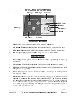
Страница 10: ...e recovery operation Vacuumize 2 When lighted indicates that the machine is generating vacuum Refilling 3 When lighted indicates that the machine is refilling the auto system New refrigerant is being added Drain 4 When lighted indicates that the machine is draining used cooling oil from the auto A C system HP Bottle Full 5 During the Recovery process when the light is on it indicates either that t...

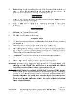
Страница 11: ...rigerant recovery operation Dur ing the Recovery operation pressing this Key will toggle the LCD display between Setup Value and Actual Recovery Value Vacuumize 4 Press this Key to initiate the vacuum generation operation Refilling 5 Press this Key to initiate the Refilling operation Start Stop 6 Press this Key to start or stop the current operation WARNING Do not use any refrigerant other than fa...

Страница 12: ... Check the vehicle compressor drive belt If it is worn or cracked it should be re 1 placed before any other service is performed Check the vehicle system hoses Look for cracks bubbles hard spots and dete 2 rioration Inspect all hoses and fittings for leaks and refrigerant seepage If there is any evidence of wear replace the damaged parts before performing any other service Note Use of a leak detec...

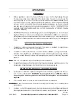
Страница 13: ...the hoses connected it is necessary to remove 1 air from the hoses and machine before beginning the recovery process To do this run the Vacuuming process Press the Vacuumize Key on the control panel The LED Display will show the 2 default time setting for the Vacuuming process Press to set Vacuuming time 3 5 minutes is recommended 3 Close the HP and LP Valves on the Control Panel 4 Press the Start...

Страница 14: ...Remove some refrigerant from the bottle before restarting the process If weight of refrigerant tank does not increase for a minute it indicates that no refrig 4 erant is being recovered This may mean the auto A C system is empty the HP or LP valve is closed a hose is blocked or other problem The process will shut down and an alarm will sound Resolve the problem before restarting the process Do not...

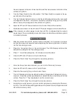
Страница 15: ...llow oil to flow into the system until 10 ml more than the amount removed has been added back When sufficient oil has flowed back into system close Oil Charge Valve 5 Press the Refilling Key on the Control Panel The machine will begin to replace 6 refrigerant in the vehicle A C system The Refilling Indicator light will be on NOTE If the refilling process is taking too long you can speed the proces...

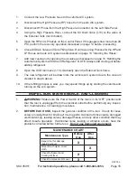
Страница 16: ...alve I 13 Gradually open the External Tank Valve 8 The new refrigerant will be drawn into the vehicle A C system due to the vacuum 9 created in step 6 above If the refilling process is slow you may speed things up by starting the vehicle and 10 turning on the A C system INSPECTION MAINTENANCE AND CLEANING 1 WARNING Make sure the Power Switch of the tool is in its OFF position and that the tool is ...

Страница 17: ...ty II 6 Mat 1 II 7 Scale Tray 1 II 8 Refrigerant Cylinder 1 III 1 Front Panel 1 III 2 Dryer and Filter 1 III 3 Separator 1 III 4 Solenoid 1 IV Right Side Panel 1 V 1 Control Panel 1 V 2 Main Control Board with LCD 1 V 3 Key Pad 1 V 4 High Pressure HP Gauge 1 V 5 Low Pressure LP Gauge 1 V 6 Cylinder Gauge 1 V 7 Low Pressure LP Valve 1 V 8 High Pressure HP Valve 1 VI 1 Back Panel 1 Please Read The F...

Страница 18: ...Page 18 SKU 95951 For technical questions please call 1 800 444 3353 Auto A C Recovery Recharge Machine Component Groups ...

Страница 19: ...Page 19 SKU 95951 For technical questions please call 1 800 444 3353 Group I Left Side Panel Assembly ...

Страница 20: ...Page 20 SKU 95951 For technical questions please call 1 800 444 3353 Group II Bottom Panel Assembly ...

Страница 21: ...Page 21 SKU 95951 For technical questions please call 1 800 444 3353 Group III Front Panel Assembly and Group V Control Panel Assembly ...

Страница 22: ... or consequential damages arising from the use of our product Some states do not allow the exclusion or limitation of incidental or consequential damages so the above limitation of exclusion may not apply to you This warranty is expressly in lieu of all other warranties express or implied including the warranties of merchantability and fitness To take advantage of this warranty the product or part...

Отзывы: