background image

Page 6

For technical questions, please call 1-800-444-3353.

Item 61373 


SAFET

y

Op
ERA
TION

M

AINTENAN

c

E

SETU
p

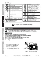
Symbology

Double Insulated

Canadian Standards Association

Underwriters Laboratories, Inc.

V

Volts

~

Alternating Current

A

Amperes

n0 xxxx/min.

No Load Revolutions per Minute (RPM)

Read the manual before 

set-up and/or use.

WARNING marking concerning Risk 

of Eye Injury.  Wear ANSI-approved 

safety goggles with side shields.
WARNING marking concerning Risk 

of Facial Injury from flying debris.  

Wear ANSI-approved full face shield. 
WARNING marking concerning 

Risk of Foot Injury.  Wear 

steel-toe work boots.
WARNING marking concerning 

Risk of Hand Injury.  Wear 

heavy-duty work gloves.
WARNING marking concerning 

Risk of Electric Shock.  

Properly connect power cord 

to appropriate outlet.

WARNING marking concerning 

Crushing Hazard.  Keep hands and 

feet away from moving parts.

 SAVE THESE INSTRUcTIONS.

Setup - Before Use:

  Read the ENTIRE IMpORTANT SAFETy INFORMATION section at the beginning of this 

manual including all text under subheadings therein before set up or use of this product.

TO pREVENT SERIOUS INJURy FROM AccIDENTAL OpERATION: 

Turn the power Switch of the tool off and unplug the tool from its electrical outlet 

before performing any procedure in this section.
Note:

  For additional information regarding the parts listed in the following pages, 

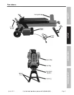
refer to the Assembly Diagram near the end of this manual.

Assembly

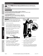
1.  Insert the Control Handle (37) through the 

slot in the Shield (32) and into the shaft 

on the Control Handle Bracket (36).

2.  Turn the Control Handle to tighten in place.

control Handle (37)

Shield (32)

control Handle 

Bracket (36)

Figure A:  control Handle Assembly

Содержание 61373

Страница 1: ......

Страница 2: ... hazardous situation which if not avoided could result in minor or moderate injury Addresses practices not related to personal injury IMPORTANT SAFETY INFORMATION General Tool Safety Warnings Read all safety warnings and instructions Failure to follow the warnings and instructions may result in electric shock fire and or serious injury Save all warnings and instructions for future reference 1 KEEP...

Страница 3: ...oggles under full face shield heavy duty work gloves and steel toe work boots during use 3 Crushing hazard Never place hands or feet between the log and splitter wedge or between the log and the ram during the forward or reverse stroke 4 Never place hands or body near a hydraulic fluid leak or check for a leak with hands or other body parts High pressure fluid can be forced under the skin resultin...

Страница 4: ...known to the State of California to cause cancer and birth defects or other reproductive harm Wash hands after handling California Health Safety Code 25249 5 et seq 23 The warnings precautions and instructions discussed in this instruction manual cannot cover all possible conditions and situations that may occur It must be understood by the operator that common sense and caution are factors which ...

Страница 5: ...ds with inadequately sized wire causes a serious drop in voltage resulting in loss of power and possible tool damage See Table A 3 The smaller the gauge number of the wire the greater the capacity of the cord For example a 14 gauge cord can carry a higher current than a 16 gauge cord See Table A 4 When using more than one extension cord to make up the total length make sure each cord contains at l...

Страница 6: ...erly connect power cord to appropriate outlet WARNING marking concerning Crushing Hazard Keep hands and feet away from moving parts SAVE THESE INSTRUCTIONS Setup Before Use Read the ENTIRE IMPORTANT SAFETY INFORMATION section at the beginning of this manual including all text under subheadings therein before set up or use of this product TO PREVENT SERIOUS INJURY FROM ACCIDENTAL OPERATION Turn the...

Страница 7: ...estions please call 1 800 444 3353 Item 61373 Safety Operation Maintenance Setup Functions Control Handle Power Switch Ram Cutting Wedge Power Cable Lift Handle Rubber Feet Guide Plate Vent Plug Drain Bolt Dipstick Front Leg ...

Страница 8: ...t Leg to raise the Log Splitter to a standing position on the wheel end of the unit Be careful not to damage the Control Handle when standing the tool upright 3 Remove the Drain Bolt Dipstick from the fluid reservoir with a hex key 4 Wipe off the Drain Bolt Dipstick and thread it back into the fluid reservoir Remove and check to make sure the fluid level is within the acceptable range between the ...

Страница 9: ...he direction of the grain on the Machine Body of the Splitter between the Guide Plates Place one end of log against the Cutting Wedge The log must be stable so that it will split properly 7 Push the Control Handle down to move the Ram forward into the log driving it onto the Cutting Wedge splitting the log 8 Release the Control Handle to retract the Ram automatically remove split log pieces and be...

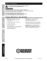
Страница 10: ...roblem corrected before further use Cleaning Maintenance and Lubrication 1 BEFORE EACH USE inspect the general condition of the Log Splitter Check for loose hardware misalignment or binding of moving parts cracked or broken parts damaged electrical wiring leaking hydraulic fluid Do not check for leaks during operation any other condition that may affect its safe operation 2 AFTER USE wipe external...

Страница 11: ...d check to make sure the fluid level is within the acceptable range between the two marks on the Dipstick Refer to Figure B Dipstick on page 8 7 Replace the Vent Plug and Drain Bolt Dipstick Tighten securely 8 Replace the Rubber Feet on the ends of the Front Leg 9 Use the Lift Handle to return the unit to its normal horizontal operating position 10 Open the Vent Plug by turning it counterclockwise...

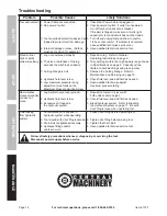
Страница 12: ...rew 1 Reposition log Refer to General Operating Instructions on page 9 2 Only split logs within the Log Capacity range shown in Specifications on page 2 Capacity will be limited on hardwood logs and green lumber 3 Sharpen the Cutting Wedge Refer to Maintenance and Servicing on page 10 4 Check fluid level and add fluid as needed 5 Have qualified technician adjust maximum pressure rating Ram vibrate...

Страница 13: ...FIED TO REPLACE ANY PARTS OF THE PRODUCT IN FACT THE MANUFACTURER AND OR DISTRIBUTOR EXPRESSLY STATES THAT ALL REPAIRS AND PARTS REPLACEMENTS SHOULD BE UNDERTAKEN BY CERTIFIED AND LICENSED TECHNICIANS AND NOT BY THE BUYER THE BUYER ASSUMES ALL RISK AND LIABILITY ARISING OUT OF HIS OR HER REPAIRS TO THE ORIGINAL PRODUCT OR REPLACEMENT PARTS THERETO OR ARISING OUT OF HIS OR HER INSTALLATION OF REPLA...

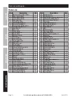
Страница 14: ...Ø14 Ø10x100x1 1 39 O Ring Ø18x1 9 2 40 Copper Seal Washer M14x1 2 41 Fluid Tube Screw M14x30 2 42 Inner Hex Bolt M8x20 4 43 Spring Washer M8x2 3 4 Part Description Qty 44 Hydraulic Pump 1 45 O Ring Ø18x1 9 1 46 Fluid Suction Tube Ø14 Ø10x100x1 1 47 Copper Seal Washer M14X1 3 48 Fluid Tube Screw M14X30 2 49 Fluid Filter 1 50 Inner Hex Bolt M8x35 4 51 Spring Washer M8x2 3 4 52 Flat Washer M8x1 4 53 ...

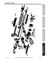
Страница 15: ...on Maintenance Setup Assembly Diagram 32 31 30 29 27 45 2 1 3 4 5 6 7 8 46 47 49 48 39 36 38 82 81 79 78 70 71 72 73 77 76 55 54 50 51 52 44 42 43 53 59 56 69 68 67 66 65 60 61 62 63 64 57 58 75 74 28 24 23 20 21 22 25 26 19 17 15 16 14 12 13 11 18 9 10 80 83 84 86 85 41 40 35 33 37 34 ...

Страница 16: ... so the above limitation of exclusion may not apply to you THIS WARRANTY IS EXPRESSLY IN LIEU OF ALL OTHER WARRANTIES EXPRESS OR IMPLIED INCLUDING THE WARRANTIES OF MERCHANTABILITY AND FITNESS To take advantage of this warranty the product or part must be returned to us with transportation charges prepaid Proof of purchase date and an explanation of the complaint must accompany the merchandise If ...

Отзывы: