


CN0182 PULSE INCREMENTAL SERVO DRIVE
LOCATION OF COMPONENTS
1
3
2
4
7
6
8
9
5
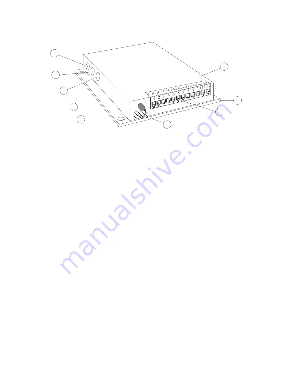
Figure 1
(1) MODULE
The CN0182 is encapsulated in epoxy and encased in an anodized aluminum cover.
Information is printed on the cover for the configuration of the Option Header and for the
electrical connections to the drive.
(2) MOUNTING PLATE
(5)
MOUNTING HOLES
The temperature of the drive must never be allowed to exceed 70
°
C (158
°
F). The Centent
HSK heat sink kit may be ordered if additional heat sinking is required. Four mounting holes
on 3.625” centers are provided to secure the drive to the heat sink or user equipment.
(3) TERMINAL BLOCK
A 12 position terminal block provides direct electrical connections to the drive; just strip the
wire, insert and tighten the screw. The motor, power supply, encoder and indexer interface
are accessed through this connector. The function of each terminal is printed on the cover
adjacent to the screw. Do not over-tighten the screws, a torque-limit driver is recommended.
(4) OPTION HEADER
The user must configure this header for encoder type and system inertia. Position Error, Fault
output and Reset input functions are also available. Header pin assignments are printed on
the cover of the drive.
(6) FAULT LED
The LED (light emitting diode) is a visual indicator of the Fault Output. The LED is on when
the Fault Output pin on the Option Header is active.
(7) DAMPING TRIMPOT
(8) GAIN TRIMPOT
(9) CURRENT TRIMPOT
These built-in trimpots are for setting motor current and tuning the servo response of the
drive. Use a small screwdriver to turn the trimpots. Do not over-torque the trimpots.
2
Содержание CN0182
Страница 4: ......