background image

3


Incorrect choice of die profile will result in tool damage and/or affect the quality of the 


crimped joint, leading to potential failure 

2.4) Cable preparation:

-  Cut the cable perpendicular to the central axis.
-  Neatly strip the insulation over a distance equal to the barrel length allowing an additional 
  10%. Ensure all traces of the insulation are removed. Avoid damage to the outer layer of con
  ductor strands.
-  Clean the conductor carefully.
-  Sector-shaped conductors must be pre-rounded 
  before crimping.

2.5) Crimping procedure: 

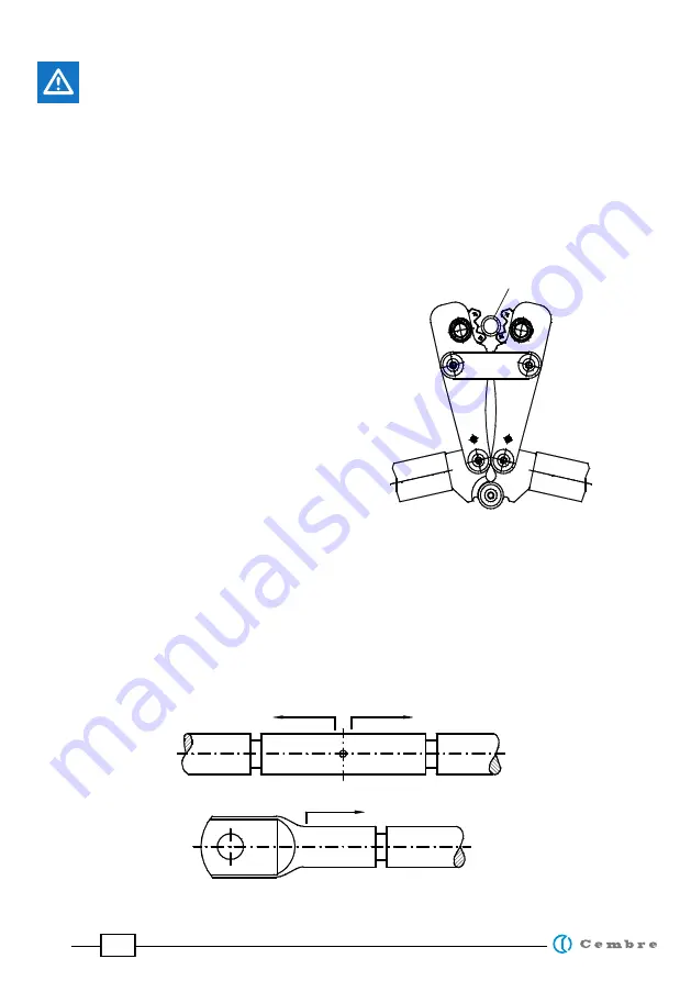
Open the crimping tool handles and position the 
connector at the lower part of the die profile (see 
image). The terminal lug/splice axis should be per-
pendicular to the plane of the die profile

-  Apply a small pressure to the handles to close the dies sufficient to trap the connector
-  Fully insert the conductor into the connector barrel.
-  Apply sufficient force to close the handles and cause the dies to compress the connector and 
  conductor until the die profiles become in contact.
-  Apply the correct number of compressions as defined on page 4, in the direction defined in 
  the figure below.
-  The crimping bite width is 5mm for these tools. 


Arbeitsrichtung beim Verpressen

DIRECTION OF THE COMPRESSIONS

Connector

Содержание TND6-70

Страница 1: ...1 MECHANICAL CRIMPING TOOL TND6 70 TNH6 70 ENGLISH OPERATION AND MAINTENANCE MANUAL 20 M 135 E ...

Страница 2: ...familiar with the instructions contained within this manual 2 2 Application Not to be used for any other purpose than for which the tools were designed Do not use these crimping tools to crimp other type of lugs or connectors 2 INSTRUCTIONS FOR USE 2 3 Die profile selection Fully open the tool handles Press down the locking pin of the indexable die plates TNH6 70 Rotate the die profiles until the ...

Страница 3: ...procedure Open the crimping tool handles and position the connector at the lower part of the die profile see image The terminal lug splice axis should be per pendicular to the plane of the die profile Apply a small pressure to the handles to close the dies sufficient to trap the connector Fully insert the conductor into the connector barrel Apply sufficient force to close the handles and cause the...

Страница 4: ...ons required per conductor size If only one compression is required please position the crimp at the midpoint of the connec tor barrel If several compressions are required these should be spaced evenly Remove dust humidity and other impurities with a clean brush or a soft cotton free cloth Never use any items which may damage the tool Take care that the bolts any moveable parts and the tool surfac...

Страница 5: ...e than required has been selected Incorrect connectors have been used Other causes Adjust die profiles to match the connector requirement Verify the connector type and size is correct Return tool to Cembre for inspec tion and repair The compression is of insufficient depth and the conductor can be pulled from the joint The die profile is larger than required Incorrect connectors type have been use...

Страница 6: ... 9018111 12 SPIRAL PIN 5X14 4 9018112 13 FILLISTER HEAD SCREW M 6X20 ZINC PLATED 1 9018113 14 FILLISTER HEAD SCREW M 6X25 ZINC PLATED 2 9018114 15 FILLISTER HEAD SCREW M 6X30 ZINC PLATED 2 9018115 16 NUT SELF LOCKING M6 4 9018116 17 WASHER 6 4 ZINC PLATED 8 9018117 18 GUIDE SLEEVE 1 1 9018118 19 GUIDE SLEEVE 2 2 9018119 20 GUIDE SLEEVE 3 2 9018120 21 DISTANCE SLEEVE 4 9018121 22 GRIP 2 6950044 23 ...

Страница 7: ...7 4 16 21 2 10 9 15 20 7 23 1 22 11 8 5 13 18 14 19 17 12 6 24 1 3 FIG 1 ...

Страница 8: ...y 8 28850 Torrejón de Ardoz Madrid España Teléfono 34 91 4852580 Telefax 34 91 4852581 E mail comercial cembre es www cembre es Cembre GmbH Heidemannstraße 166 80939 München Deutschland Telefon 49 89 3580676 E mail info cembre de www cembre de Cembre Inc Raritan Center Business Park 300 Columbus Circle Suite F Edison New Jersey 08837 USA Tel 1 732 225 7415 Fax 1 732 225 7414 E mail sales US cembre...

Отзывы: