


3
HYDRAULIC PRESSHEAD
RHU240-3D-850
1. GENERAL CHARACTERISTICS
– Application range:
suitable for installing compression connectors for conductors up
to
.............................................................................................. 30
mm
2
(1250 MCM)
– Crimping force:
................................................................................................................240 kN
(27 sh ton)
– Max. operating pressure:
............................................................................................850 bar (12,150 psi)
– Oil necessary
(displacement)
:
....................................................................................63 cm
3
(3.84 cu. in.)
– Dimensions:
length .......................................................................................................283 mm (11.1 in.)
width
.........................................................................................................129
mm (5.0
in.)
– Weight
(without dies)
:
...................................................................................................5,5 kg
(12.1 lbs)
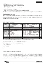
The adapter
AU240-130D
is available as an optional extra enabling the head to utilise the semi-circular
slotted dies common to most 130 kN tools.
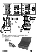
2. INSTRUCTIONS FOR USE
2.1) Setting
(Ref. to Fig. 1)
The head is equipped with a "self-lock" quick male coupler and can be connected to a
Cembre
hydraulic pump developing
850 bar
pressure.
For safe operation a safety shackle (04) is provided for additional support.
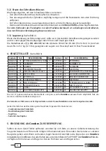
2.2) Die insertion
a) Dedicated dies
(Ref. to Fig. 1)
– Select the appropriate die set for the connector to be crimped.
– A checkplate (60) aligns the upper die with the die locating pin (12).
Dies without the checkplate (60) may be inserted into the head by manually aligning the die
locating pin (12) in the die.
– Extract the die locating pin (12) from the head.
– First, insert the lower die (32a) into the fork (11) and align the groove in the die with the guide
screw (15) in the fork (11).
– Then fi t the upper die into the head and insert the die locating pin (12).
– To remove the dies from the head, extract the die locating pin (12) and slide out the dies.
ENGLISH