background image

18

2

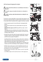
11

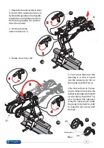
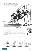
Rotate the blue lever (18) in order 

to lock it in the external position, to 
facilitate this operation it is advisable 
to keep the arm slightly raised from 
the base by gripping it in position 
(A) with one hand.

2

 - 

At the same time 

unlock red lever (17).

3

 - 

Rotate the arm by 180°.

18

17

A

3

5

4

4

 - 

First re-lock blue lever (18) 

releasing it so that it inserts 
into the opposite slot (A) on 
the sliding track (Ref. Fig. a).

5

 -

Re-lock red lever (17) relea-

sing it so that it inserts into the 
diametrically opposite hole (B) 
on the sliding track (Ref. Fig. 
a); to facilitate this operation 
it may be necessary to rotate 
the group (C) by hand in order 
to make the pin line up with 
the hole.

(B)

(A)

         Sliding track

17

(C)

17

18

18

Fig. a

Содержание RDS-14P

Страница 1: ...1 RDS 14P RDS 14P 78 ĞƌƟĮĞĚ ŶǀŝƌŽŶŵĞŶƚĂů DĂŶĂŐĞŵĞŶƚ LJƐƚĞŵ ĞƌƟĮĞĚ KĐĐƵƉĂƟŽŶĂů ĞĂůƚŚ Θ ĂĨĞƚLJ DĂŶĂŐĞŵĞŶƚ LJƐƚĞŵ ĞƌƟĮĞĚ YƵĂůŝƚLJ DĂŶĂŐĞŵĞŶƚ LJƐƚĞŵ RAIL SAW ENGLISH 14 M 113 E PATENT PENDING ...

Страница 2: ...ineandmustbeproperlyinformed about its use and the risks arising from improper use which could cause injury or even death Complywithappropriaterestperiodsandavoidprolongedexposure to vibrations and noise Duringcutting dustandwasteparticlesarereleased includingexhaust gas and petrol fumes which can be inhaled Keep the rail saw firm during manual cutting in order to avoid hazar dous kickback When cut...

Страница 3: ...r personnel not operating the machine should be at least 15 metres Hot sparks which fly off during cutting can cause fire if in the presence of flammable materials such as dry grass petrol wood etc The RAIL SAW must only be used in conjunction with support arms supplied by Cembre Never operate the RAIL SAW during personal ill health when tired or under the effects of alcohol drugs or medicines whi...

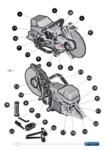
Страница 4: ... pin Descriptions and possible configurations Rail saw suitable for cutting discs with hub diameter of 22 2 mm 7 8 RDS 14P RDS 14P 78 AA RDS SA RDS RDS 14P AA RDS 14P 78 AA RDS 14P SA RDS 14P 78 SA 14 4mm Allen key for removing side guard 15 Auxiliary switching device 16 Multifunction spanner torx cut 17 Fuel tank cap 18 Main ON OFF switch 19 Rear control handle 20 Accelerator 21 Safety lever 22 Ac...

Страница 5: ...5 FIG 1 4 3 1 2 8 12 8 21 22 23 5 9 24 15 19 6 11 10 7 16 17 20 18 7 26 27 13 13 25 25 14 ...

Страница 6: ...drive shaft diameter RDS 14P 25 4 mm 1 drive shaft diameter RDS 14P 78 22 2 mm 7 8 max diameter of suitable cutting disc 406 mm 16 max cutting depth 140 mm 5 5 Acoustic noise Directive 2006 42 EC annexe 1 point 1 7 4 2 letter u The weighted continuous acoustic pressure level equivalent A at the work place LpA is equal to 105 5 dB A The maximum value of the weighted acoustic displacement pressure C...

Страница 7: ...out pressing this lever When the accelerator is released the abrasive cutting disc continues to turn for some time Do not approach the cutting group until the disc has completely stopped ACCELERATOR BLOCK 22 has two functions it locks the accelerator in start up position when the engine is cold it locks the accelerator in maximum acceleration position This function must only be used in automatic m...

Страница 8: ...sion in order to reset the alarm code With each pulse the machine will beep in recognition If the device is not able to control the machine check there are no obstacles between the device and the machine move much closer to the machine it is likely that you are out of range fully accelerate the machine for at least 10 seconds replace the old battery mod CR2032 with a new one Replacing the battery ...

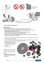
Страница 9: ...tting discs must only be used for cutting suitable materials During transportation and storage of the rail saw always remove the cutting disc and lay it on a flat surface in a dry place protected from frost and moisture Always tighten the fixing screw of the cutting disc with a 20 25 Nm torque to prevent the disc from loosening Worn or broken discs must be disposed of in compliance with local statut...

Страница 10: ...ngine oil and a minimum 90 octane Petrol Mix petrol and oil together well and prepare only enough for immediate use as the mixture will age and if several weeks old may cause engine damage Always use the correct fuel mixture to avoid 1 Smoking engine and dirty spark plug should the mixture be too oil rich 2 Excessive overheating with consequent seizing of the engine should the mixture be oil defici...

Страница 11: ...engine only when the abrasive cutting disc is mounted With the 13 mm multifunction spanner supplied unscrew the locking screws 12 and retrieve the pressure plate S Mount the disc on the shaft inside the safety guard so that it rests on the central stop Mount the pressure plate and lock all the screws 12 tightening with a 20 25 Nm During the tightening phase counteract the movement of the disc with...

Страница 12: ...inst the ground Gently pull the starter rope until you feel some resistance the starter hooks will kick in and then pull vigorously with rapid and decisive movements until the engine starts Note To avoid damaging the winding device accompany the starter rope in the return phase and do not pull it over its stroke With the engine running press and immediately release the acce lerator to unlock it fr...

Страница 13: ... of the work phase Cutting line Thereferenceplate 5 isessentialforexactlylocating the cutting line on the rail The length of the plate depends on the machine support arm assembly On the first cut it is necessary to establish an ori gin of the cutting distances by removing excess plate Push plate 5 hard until it comes into contact with the fixed jaw 16 Cut the rail Ref to 7 or 9 the excess part of th...

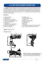
Страница 14: ...t handle 2 Sliding tracks 3 Suspension for cut loading 4 Disc movement adjustment ring 5 Cutting reference plate 6 Mobile jaw 7 Locking unlocking handwheel 8 Motion transmission gear 9 Rail saw locking pin Weight 19 8 kg 43 5 lbs Dimensions mm h S ll h h l h 491 354 586 112 445 170 544 10 Reference pin 11 Interface rotation lever 12 Mobile arm 13 Rail saw locking handle 14 Stabilising rods 15 Fixe...

Страница 15: ...15 Serial Number Numéro de série Seriennummer Número de serie Numero di Matricola xxxxxx 1 5 13 14 7 6 2 9 5 12 15 xxxxxx 4 3 11 17 16 8 10 18 ...

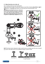
Страница 16: ...nting the rail saw on the arm check that the clamp is positioned and locked in a correct manner on the rail head Ref Fig b Ifthearmiswronglypositioned itcancausecut tingwhichisnotperfectlystraight Ref Fig c d NOTE The fixing clamp is designed to allow a precise and secure tightening of the arm onVignole type rails for the fixing of the arm on different rail types contact Cembre Type Vignole Contact C...

Страница 17: ... be cut type UIC 60 or similar The adjustment ring 4 can be rotated in both directions along a graduated scale from 0 to 50 on one face of the hexagon is a corresponding reference mark Pos 0 no load suspension corresponds to the maximum force at the cutting point the rail saw presses on the rail much more Pos 50 maximum load suspension corresponds to the minimum force at the cutting point Adjustme...

Страница 18: ... 17 3 Rotate the arm by 180 18 17 A 3 5 4 4 First re lock blue lever 18 releasing it so that it inserts into the opposite slot A on the sliding track Ref Fig a 5 Re lock red lever 17 relea singitsothatitinsertsintothe diametricallyoppositehole B on the sliding track Ref Fig a to facilitate this operation it may be necessary to rotate the group C by hand in order to make the pin line up with the ho...

Страница 19: ...ible click will confirm that the operation has been performed correctly NOTE forpracticalreasons werecommendtheinterface unitisrotatedbeforeoverturning inanycaseitisimportant that at the end of rotation the transmis sion gear 8 is positioned at the low point G 11 8 8 8 IMPORTANT Ref to figure below Make sure that at the end of rotation lever L is resting on the bushes A so that the spring rod is po...

Страница 20: ...r match with the slots on the two sides of the rail saw 2 Push and rotate the handle 13 tightening it fully To dismount the rail saw completely loosen the handle 13 and remove it from the arm 6 4 Mounting dismounting the rail saw on the automatic support arm Before mounting the rail saw on the support arm Check the gear 8 is in the downward position as described in 6 3 1 Make sure clamp 6 is firmly...

Страница 21: ...pecial reference plate NOTE Check that the plate is pushed into contact with the clamp during a first cut it is necessary to define the exact origin of the distances by cutting the reference plate Ref to 5 Mount the rail saw onto the arm Ref to 6 4 and start the engine Ref to 4 4 Operate the accelerator Press accelerator block 22 Ref to 3 2 to maintain maxi mum acceleration for at least 10 seconds b...

Страница 22: ...omatically turn off due to an electronic system which detects the rpm variation of the engine Unlock the accelerator from the maximum acceleration position by pressing it right down Lift the arm and put it back into stationary position re locking the blue lever 18 NOTE Some factors such as diameter of the cutting disc a partially worn disc and dimensions of a full cut can influence the cutting opera...

Страница 23: ...the rail to take up the cut easily and precisely Weight 8 5 kg 18 7 lbs Dimensions mm If the rail saw stops at the rail head shortly after starting the cut it means that the cutting force is toohigh rotatetheadjustmentringacoupleofturnstowardshighervaluesinordertoputmore load on the contrast spring If the rail saw stops at the intersection between the rail web foot towards the end of the cut it me...

Страница 24: ... 2 4 1 3 6 7 8 5 Description 1 Rail saw locking handle 2 Mobile arm 3 Sliding track 4 Clamp locking wheel release 5 Cutting reference plate 6 Fixed jaw clamp 7 Stationary positioning lever 8 Knob to adjust arm height 9 Vertical arm 10 Mobile jaw clamp 11 Rail saw interface pin 9 5 11 10 8 ...

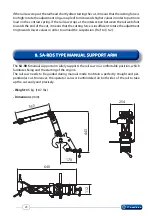
Страница 25: ... 2 2 2 1 1 8 8 The SA RDS manual support arm can be overturned from one side to the other without needing to be removed from the rail to allow a comfortable and precise re sumption of cutting To carry out this operation it is sufficient to grasp it at point A rotate it by 180 and move it so that it rests on the opposite side the re ference 8 has to rest on the clamp 6 Before mounting the rail saw on...

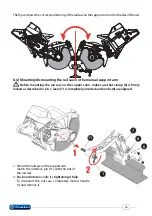
Страница 26: ...l saw completely loosen handle 1 and remove it Thefigureshowsthecorrectpositioningoftherailsawonthesupportarmonbothsidesoftherail 8 4 Mounting dismounting the rail saw on the manual support arm Before mounting the rail saw on the support arm make sure that clamp 6 is firmly locked as described in 6 1 lever 7 is completely inserted and knobs 8 are aligned 7 6 1 11 8 ...

Страница 27: ...of the cutting distances must be defined exactly Refer to 5 Mount the rail saw onto the arm Ref to 8 4 Start the engine Ref to 4 4 Operate the accelerator to maintain maximum acceleration for at least 10 seconds before starting to cut Support the rail saw by holding the upper handle with one hand and with the other hand pull out lever 7 locking it in the external position to release the arm Press ...

Страница 28: ...alter nate movements maintaining a steady pressure during the whole cutting phase Thedoublearticulationofthesupportarm will relieve the operator of the weight of the machine thus making the cutting operation easier Once the operation is finished release the accelerator lift the rail saw and re lock the arm in its resting position by pushing in the lever 7 fully Switch off the engine by using the swi...

Страница 29: ...ndle firmly Approach the rail carefully at the start of the cutting operation With a cut that has already been started insert the disc very carefully at maximum speed Pull in Pull in occurs when the cutting disc catches unexpectedly during operation and the rail saw is violentlypulleddownwards thiscanhappenifthe cut closes and the disc jams To avoid pull in ensure that the cut stays open during the...

Страница 30: ...ccelerator block auxiliary switching device the disc guard The cutting disc is not damaged After usage Clean the machine and support arms with a clean rag to remove dust and cutting waste Clean the air filters on the engine s side and transmission cover Weekly Check The fixing of the muffler The state and wear of the belts Refer to 10 8 The carburettor is working The start up devices cable counter spr...

Страница 31: ...chine not being able to carry out cutting in automatic mode Primary sponge filter S spare part code 6003910 Remove the top engine cover by unscrewing the 2 Torx screws with the tool supplied Take the filter out and wash it carefully with warm water and soap then rinse it well with clean water Squeeze the filter well and dry it Before remounting it carefully oil the filter It is important that the filte...

Страница 32: ...003922 A reduction in fuel flow towards the carburettor indicates that the filter is clogged up The fuel filter is located in the fuel tank and if it is clogged up it must be replaced with a new one as it cannot be cleaned Avoid dirt getting into the fuel tank during filter replacements Replace the fuel filter at least once a year 10 3 Spark plug spare part code 6003752 Deposits on the spark plug s ele...

Страница 33: ...justment is necessary turn it clockwise until there is nofuelintheengine thenopenit1 8turnanticlockwise Check engine acceleration NOTE A poor adjustment of low speed screw L too tight can cause difficulty when starting the engine Final adjustment of minimum speed T The engine s minimum speed is adjusted through screw T If an adjustment is required turn clockwise until the cutting disc starts to turn...

Страница 34: ...round the cavity Ref to Fig c Put the pulley back onto the recoil spring so that the end of the spring clasps the pulley and re attach with the screw in the centre Thread the starter rope through the hole in the side cover and the starter handle Make a knot at the end of the rope Refer to Fig d Tensioning the recoil spring Remove the starter rope through the notch on the side of the pulley and rot...

Страница 35: ...dailybasisitisgoodpractice tocheckthattheseopeningsareperfectlycle an Ifnecessary cleanthemwithcompressed air or a soft brush The filter on the lower part of the cover prevents cutting particles and debris being conveyed inside the transmission area Cleaning the cover filter spare part code 6003655 Disassemble the side cover by remo ving 5 screws with the 4 mm Allen key supplied Remove the filter and...

Страница 36: ... belt 1 Place the belt on the drive shaft pulley behind the rear pinion 2 Thread it behind plate P and under rolls R and place it against the front split pulley Assemble the fan group polarizing it with respect to the two faces of the drive shaft and lightly screw it into place NOTE Duringreassembly firstlymanually alternateblockingandrotationofthedisc This will counter the rotation of the drive sh...

Страница 37: ...xture correctly see 4 1 Check the carburration 10 4 Add fuel to tank see 4 2 Clean if necessary replace see 10 1 10 2 Prepare fuel mixture correctly see 4 1 Prepare mixture with more oil Clean the cooling fins Check engine for seizure contact Cembre 13 Prepare mixture with less oil Clean spark plug if necessary 10 3 Check the wear and tear 10 6 Contact Cembre 13 Clean if necessary replace see 10 1 ...

Страница 38: ... 6 in weight 12 kg 26 4 lbs VAL AA RDS container for storing the automatic support arm Dimensions 910 x 415 x h420 mm 35 8 x 16 3 x 16 5 in weight 7 kg 15 4 lbs If transporting the machine or if it is not used for a long period of time empty the fuel tank and store the machine in a dry and safe place which is not accessible to children or unauthorised persons During transportation and storage of t...

Страница 39: ...upplied by Cembre together with the machine or if no other references are available indicate the approximate purchase date and the machine serial number In the case of a breakdown contact our area agent who will advise you on the problem and max 858 33 7 max 959 37 7 280 11 448 17 6 ø 4 0 0 m m 850 33 5 95 3 7 365 14 4 150 5 9 910 35 8 UIC 60 815 32 FIG 3 OVERALL DIMENSIONS with automatic arm mm i...

Страница 40: ...23 Morangis Cédex E mail info cembre fr www cembre fr Cembre España S L Calle Verano 6 y 8 P I Las Monjas 28850 Torrejón de Ardoz Madrid España Teléfono 91 4852580 Telefax 91 4852581 E mail comercial cembre es www cembre es Cembre GmbH Heidemannstraße 166 80939 München Deutschland Telefon 089 3580676 Telefax 089 35806777 E mail sales cembre de www cembre de Cembre Inc Raritan Center Business Park ...

Отзывы: