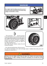
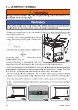
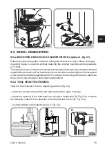
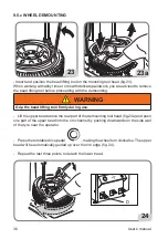
background image

User’s manual 

23

EN

4. MoUnTInG

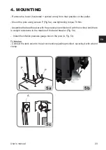
- Remove the tower (hori vertical arms) from their position on the pallet.

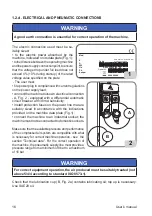
- Mount the pole using screws P (Fig.5a), use tightening torque 70 Nm.

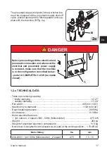
- Assemble the bead breaker with the proper pin and fasten it with the locknut until there 

is a slight resistance in the rotation of the bead breaker (Fig. 5b).

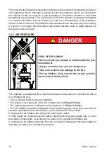
-  Install the infl ation pressure gauge box on the pole (A, Fig. 5c).

T.I Version

- Connect the tank union to the air connection pipeline provided, securing it with a band 

clamp. 

5c

A

5b

5a

P

P

Содержание SM628TI

Страница 1: ...41 706369 Fax 39 0341 700725 www cemb com garage cemb com Cemb Spa declines all liability for any damage to people or property caused by incorrect use of this product Subject to change without prior n...

Страница 2: ...uction Manual should be considered an integral part of your equipment and should remain with the equipment However nothing in this manual and none of the devices installed on the equipment can replace...

Страница 3: ...nternal external locking with steel jaws Bead breaking Standard wheels Low profile wheels Demounting Standard wheels with plastic guards for tool head and lever Proper tool head positioning to avoid d...

Страница 4: ...__________________ ___________________________________________________ ___________________________________________________ ___________________________________________________ _________________________...

Страница 5: ...S mm 27 8 MAIN WORKING ELEMENTS OF THE MACHINE 28 8 1 COMMANDS 28 9 BASIC PROCEDURES USE 30 9 1 PRELIMINARY CHECKS 31 9 2 DECIDING FROM WHICH SIDE OF THE WHEEL THE TYRE MUST BE REMOVED 31 9 3 BEAD BRE...

Страница 6: ...dures and maintenance Italics are used to refer to specific parts of this manual that offer additional information or clarifications These references must be read in order to obtain information additi...

Страница 7: ...nstructions it contains are not observed This manual makes continuous reference to the possibility that accidents can occur Any accident could lead to serious or fatal injuries to the operator or peop...

Страница 8: ...of mount demount head during operation Keep your hands and other body parts away from moving parts Do not use tools other than those supplied with tyre changer Use lubricant that is specific for tyres...

Страница 9: ...Always use OSHA CE approved and authorised personal protective equipment PPE or equipment with equivalent certifications while ope rating the machine Consult your supervisor for additional instruction...

Страница 10: ...XX XXXXXXXXX ANNO DI COSTRUZIONE MANUFACTURED Mod V A kW Hz Ph bar psi LABEL MODEL SERIAL NUMBER 02 000101100 LABEL ROTATION TURNTABLE LABEL TURNTABLE OPE NING CLOSING LABEL BEAD BREAKER ACTIVATION 0...

Страница 11: ...ularly as outlined in the instruction manual F Remove all air from tire before loosening beads Remove valve core G Remove all wheel weights from rim before mounting or demounting to prevent damage H A...

Страница 12: ...OCK DO NOT EXPOSE THIS TIRE CHANGER TO RAIN WATER OR WET LOCATIONS WARNING THIS TIRE CHANGER DOES NOT CONTAIN USER SERVICEABLE PARTS DO NOT OPEN COVER DO NOT TAMPER WITH COMPONENTS FAILURE TO COMPLY M...

Страница 13: ...t n 000103300 LABEL HAND CRUSHING HA ZARD BEAD BREAKER part n 000103400 LABEL LEG CRUSHING HAZARD BEAD BREAKER part n 000102900 LABEL RISK OF INJURY REAR POLE part n 000103100 LABEL DANGER TOOL HEAD L...

Страница 14: ...rim carefully for defects Do not mount the tire if any defects are found G Seat beads and inflate the tire with short bursts of air while continuously checking the air pressure H Stand away from the t...

Страница 15: ...User s manual 15 EN 01 05 02 06 07 08 18 09 14 21 21 04 12 11A 11B 10 17 16 15 19 03 20...

Страница 16: ...ivity install protection fuses on the power line that are suitably sized in accordance with the indications provided on the machine data plate Fig 1 connect the machine to an industrial socket the mac...

Страница 17: ...configuration described below pedal A COMPLETELY LOW turntable closed A 1 2 e TECHNICAL DATA Table top clamping capacity inside clamping 14 27 outside clamping 11 24 Rim width 405 mm 15 5 Maximum tyr...

Страница 18: ...tyre and rim dimensions Take care to avoid any damage to the tyre During inflation keep outside the vertical cylinder area occupied by the wheel The machine is equipped with an internal pressure limi...

Страница 19: ...e wheels unless they have received suitable training regarding the correct maintenance procedures for the type of wheel being serviced and the operative safety procedures Information to be used for th...

Страница 20: ...he machine if it is placed out of service for tune up maintenance lubrication etc 1 7 DURING USE If strange or unusual noises are heard or any unusual vibration is detected if a compo nent or system i...

Страница 21: ...e Standard version 250 kg TI version 260 kg Ambient conditions for machine transport and storage Temperature 25 55 C WARNING Do not stack other goods on top of the packing to avoid damaging it Handlin...

Страница 22: ...coulddamage the machine and compromise operator safety WARNING Before removing the machine from the pallet make sure the items shown below have been removed Remove the upper part of the package and ma...

Страница 23: ...ning torque 70 Nm Assemble the bead breaker with the proper pin and fasten it with the locknut until there is a slight resistance in the rotation of the bead breaker Fig 5b Install the inflation press...

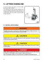
Страница 24: ...chine in compliance with all the applicable safety standards in cluding but not limited to those issued by OSHA CAUTION IMPORTANT for the correct and safe operation of the equipment the ambient lighti...

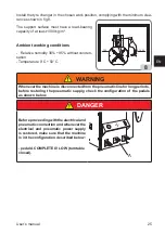
Страница 25: ...n sation Temperature 0 C 50 C WARNING Whenever the machine is disconnected from the pneumatic line for long periods before restoring the pneumatic supply check the configuration of the pedals as shown...

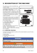
Страница 26: ...Volts A Input voltage in Amperes kW Absorbed power in kW Hz Frequency in Hz Ph Number of phases bar psi Operating pressure in bar and or psi Serial No machine serial number ISO 9001 company Quality S...

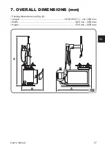
Страница 27: ...User s manual 27 EN 7 OVERALL DIMENSIONS mm Packing dimensions vedi fig 10 Length 1070 1350 T I min 1450 max Width 1020 min 1350 max Height 1700 min 2050 max B A H 10...

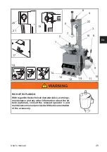
Страница 28: ...ad 8 Air lubricator 9 Bead breaker arm 10 Bead breaker 11 Wheel support 15 Tyre lever 16 Shoe guard option 17 Inflator pedal for t i version 18 Air tank 19 Swivelling arm adjustment handle 8 1 COMMAND...

Страница 29: ...11 12 13 14 18 22 WARNING RISK OF EXPLOSION With regard to the technical characteristics warnings maintenance and any other information about the air tank optional consult the relevant operator s and...

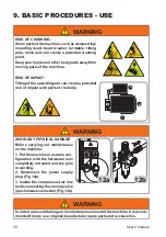
Страница 30: ...risk of impact with parts of the body B A C P P WARNING AVOID ANY PHYSICAL DAMAGE Before carrying out maintenance on the machine 1 Put the machine in a stable con figuration with the horizontal axis c...

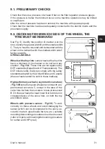
Страница 31: ...alloy rims have a minimum A rim channel or do not have any channel Fig 13A These rims are not approved by DOT standards Department of Transportation The DOT initials certify that tyres comply with th...

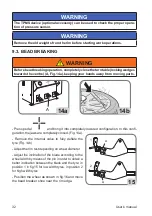
Страница 32: ...14b 14a A Press pedal and bring it into completely lowered configuration In this confi guration thejawsarecompletelyclosed Fig 14a Remove the internal valve to fully deflate the tyre Fig 14b Adjust th...

Страница 33: ...e bead at several points to free it completely Release the pedal to reverse the motion of the bead breaking shoe After detaching the beads remove the old balancing weights Thoroughlylubricatethesideso...

Страница 34: ...rol pedal and move it to the central position Fig 18 In this configuration it is possible to carry out dead man control of jaws opening and then stop them in the desired position If the rim is blocked...

Страница 35: ...ench pulltheheaddown mounttheotherheadandtightenthehexagonal screwusingthestandardsuppliedwrench Foracorrectfunctioningofthedevice takecare there are no plays between head and hexagonal bar 9 5 b TOOL...

Страница 36: ...emounting WARNING Grip the bead lifting tool firmly during use Lift the upper bead above the rear part of the demounting tool head fig 23a and push one part of the upper bead into the rim channel by p...

Страница 37: ...mbination is correct in terms of compatibility tubeless tyre on tubeless rim tyre type with inner tube on rim for inner tube and geometric dimension shrinkage diameter width cross section off set and...

Страница 38: ...make it easier to mount demount low profile tyres itisadvisedtousethebeadpressergrip per optional accessory supplied on request 9 7 TYRE INFLATION 9 7 a Safety Indications DANGER RISK OF EXPLOSION Nev...

Страница 39: ...xplode producing hazardous flying debris that may result in an accident 2 Tyres and rims that do not have the same diameter are mismatched Never attempt to mount or inflate any tyre and rim that are m...

Страница 40: ...The tyre changer is not a safety device and does not prevent tyres and rims from exploding Keep all persons not working on the machine out of the working area 9 7 b TYRE INFLATION Make sure the wheel...

Страница 41: ...reviously and check again 30 31 32 WARNING Risk of explosion During the bead insertion phase do not exceed the maximum pressure indicated by the manufacturer on the sidewall of the tyre Once the bead...

Страница 42: ...pedtotheturntable from the inner side fig 34 Lower the vertical arm until it touches the rim fig 29 then clamp the arm in this position Remove the valve core if it has not already been removed Fig 30...

Страница 43: ...y after making sure that the rim is correctly blocked WARNING RISK OF EXPLOSION Do not mount a tyre and a rim that do not have the same diameter e g 16 and 1 2 inch tyre and a 16 inch rim If the tyre...

Страница 44: ...e plug The motor is not running Check the microswitches of the pedal unit only for motor inverter Check the motor rotation control of the pedal unit Replace the inverter board only for motor inverter...

Страница 45: ...to break beads and leaks air Silencer plugged Replace the silencer Cylinder seals worn Replace the seals Replace the bead breaker cylinder After clamping the tool head does not rise or rises too far...

Страница 46: ...Before carrying out any regular maintenance operation or topping up with lubricant disconnect the machine from the compressed air supply line WARNING The manufacturer declines all responsibility for c...

Страница 47: ...AE20 oil equal to 50cc The filter regulator FR has an automatic condensation drain system therefore in condi tions of normal use special maintenance is not required The condensate may however be drain...

Страница 48: ...applies to equipment with the barred bin symbol on the rating plate This product may contain substances that are potentially harmful to the environment and human health unless disposed of properly The...

Страница 49: ...prove quality of life by preventing the discharge of potentially hazardous substances into the environment 14 INFORMATION AND WARNINGS ABOUT OIL Disposal of waste oil Never pour waste oil in sewers s...

Страница 50: ...ty of running water and seek medical attention immediately Skin wash with soap and water 15 FIREFIGHTING EQUIPMENT TO BE USED Refer to the table below to choose the most suitable fire extinguisher 16...

Страница 51: ...tions 2 Edge or bracing It is an insert of metallic or textile fabric placed at the outer part of the bead it is used to protect the carcass plies from sliding against the rim 3 Casing This is the res...

Страница 52: ...all which is more exposed to accidental rubbing 8 Sidewall This is the area between the shoulder and the centring band It consists of a more or less thin layer of rubber which protects the casing plie...

Страница 53: ...e section in contact with the tyre It is made with dif ferent geometric shapes that serve to ensure easy assembly of the tyre inserting the bead into the channel safety on the move in terms of anchori...

Страница 54: ...ing tool A tool intended for use when mounting the top bead It is positioned so that it engages the shoulder of the rim and maintains the upper tyre bead inside the well It is generally used for mount...

Страница 55: ...12 x 9 10 x 7 8 x 5 6 x 3 4 x 1 2 L 0 R 1 2 3 L1 ELEMENTI Elements CONTATTI Contacts W2 U1 U2 V2 V1 W1 W2 U1 U2 V2 V1 W1 200 220 240V 380 415 440V MORSETTIERA Junction Box F F F Power Phase 400V 3 50...

Страница 56: ...x 9 10 x 7 8 x 5 6 x 3 4 x 1 2 L 0 R 1 2 3 ELEMENTI Elements CONTATTI Contacts F F Power Phase Neutral 230V 1 50 Hz 250V 16A 250V 16A 240V 1 50 Hz 250V 16A 250V 16A 220V 1 60 Hz 250V 16A 250V 16A 115...

Страница 57: ...1 3 5 7 9 11 2 4 6 8 10 12 13 15 17 19 21 23 14 16 18 20 22 24 L2 23 24 x x x 21 22 x 19 20 x 17 18 x x 15 16 x x 13 14 x 11 12 x 9 10 x 7 8 x x 5 6 x x 3 4 x 1 2 L2 L1 0 R 1 2 3 4 5 6 V2 U2 W2 W1 V1...

Страница 58: ...R MOTOINVERTER VERSION AP1 N PE L1 F F XS1 L1 N SQ3 XB1 SQ1 SQ2 M1 R T S 1 2 3 4 U V W MARRONE NERO AZZURRO GRUPPO MOTORE MOTOR UNIT GRUPPO COMANDI CONTROL SWITCH Power Phase Neutral 200 230V 1 50 60...

Страница 59: ...D VALVE 07 CILINDRO STALLONATORE BEAD BREAKING CYLINDER 08 VALVOLA AUTOCENTRANTE SELF CENTERING CHUCK VALVE 09 RACCORDO GIREVOLE ROTATING UNION 10 CILINDRO AUTOCENTRANTE SELF CENTERING CHUCK CYLINDER...

Страница 60: ...Note...

Страница 61: ...Note...

Страница 62: ...entmanueld utilisationdoit treconsid r commepartieint grantedel quipement et devra toujours l accompagner Toutefois aucun l ment contenu dans le pr sent manuel et aucun dispositif install sur l quipem...

Страница 63: ...envers Blocage interne externe avec griffes en acier D talonnage Roues standard Roues surbaiss es D montage Roues standard avec protections en plastique pour t te op rante et levier Positionnement cor...

Страница 64: ..._______________________ ___________________________________________________ ___________________________________________________ ___________________________________________________ ____________________...

Страница 65: ...MENTS PRINCIPAUX DE FONCTIONNEMENT 88 8 1 COMANDS 88 9 PROC DURES DE BASE UTILISATION 90 9 1 CONTR LES PR LIMINAIRES 91 9 2 TABLIR DE QUEL C T DE LA ROUE D MONTER LE PNEU 91 9 3 DETALLONAGE 92 9 4 BLO...

Страница 66: ...ures et l entretien L italique est utilis pour se r f rer des parties sp cifiques du pr sent manuel qui fournissent des informations compl mentaires ou des claircissements Ces r f rences doivent tre l...

Страница 67: ...mauvaise ex cution des proc dures d entretien fournies dans le pr sent manuel ou l inobservation des autres instructions pourrait provoquer des accidents Ce manuel contientdesnotesfaisant continuellem...

Страница 68: ...u d monte pneu Tenir les mains et les doigts l cart du bord de la jante durant le processus de d montage et de montage Tenir les mains et les doigts l cart de la t te durant le fonctionnement Tenir le...

Страница 69: ...sur la capacit de faire fonctionner la machine en toute s curit 17 Toujours porter les quipements de protection individuelle EPI ho mologu s et autoris s OSHA CE ou avec des certifications quivalente...

Страница 70: ...ONE MANUFACTURED Mod V A kW Hz Ph bar psi AUTOCOLLANT NUM RO DE S RIE MOD LE 02 000101100 AUTOCOLLANT ROTATION AUTOCENTREUR AUTOCOLLANT OUVERTU REFERMETURE AUTOCEN TREUR AUTOCOLLANT ENTRA NE MENT D TA...

Страница 71: ...clothing away from moving parts E Service machine regularly as outlined in the instruction manual F Remove all air from tire before loosening beads Remove valve core G Remove all wheel weights from ri...

Страница 72: ...RIC SHOCK DO NOT EXPOSE THIS TIRE CHANGER TO RAIN WATER OR WET LOCATIONS WARNING THIS TIRE CHANGER DOES NOT CONTAIN USER SERVICEABLE PARTS DO NOT OPEN COVER DO NOT TAMPER WITH COMPONENTS FAILURE TO CO...

Страница 73: ...LLANT DANGER D CRASEMENT DES MAINS D TALONNEUR part n 000103400 AUTOCOLLANT DANGER D CRASEMENT DES JAMBES D TALONNEUR part n 000102900 AUTOCOLLANT DANGER DE COLLISION DU POTEAU ARRI RE part n 00010310...

Страница 74: ...arefully for defects Do not mount the tire if any defects are found G Seat beads and inflate the tire with short bursts of air while continuously checking the air pressure H Stand away from the tire a...

Страница 75: ...Manuel d utilisation 75 FR 01 05 02 06 07 08 18 09 14 21 21 04 12 11A 11B 10 17 16 15 19 03 20...

Страница 76: ...ction de la ligne d alimentation ayant un amp rage conforme aux indications sp cifi es sur la plaque des donn es de la machine Fig 1 brancher la machine une prise de type industriel le raccordementaux...

Страница 77: ...nesetrouvedanslaconfiguration ci dessous indiqu e p dale A TOUT EN BAS autocentreur ferm A 1 2 e DONN ES TECHNIQUES Plage des dimensions de la roue interne 14 27 externe 11 24 Largeur max du pneu 405...

Страница 78: ...s de la jante soient compatibles Faire attention aux risques de l sions du pneu Pendant le gonflage tenir une position en dehors du volume cylindrique vertical occup par la roue La machine est dot e d...

Страница 79: ...rateurs n interviennent pas sur les roues moins qu ils n aient t ad quatement form relativement aux proc dures correctes d en tretien sp cifique du type de roue sur lequel ils interviennent et aux con...

Страница 80: ...fectu correctement ces contr les pr liminaires Ne pas utiliser la machine mise hors service pour la mise au point l entretien la lubrification etc 1 7 PENDANT L UTILISATION Si l on per oit des bruits...

Страница 81: ...llage Version TI 340 kg Conditions du milieu de transport et stockage de la machine Temp rature 25 55 C ATTENTION Pour viter tout endommagement ne pas superposer d autres colis sur l emballage Manuten...

Страница 82: ...oquer des endommagements la machine et compromettre la s curit des op rateurs ATTENTION Avant de retirer la machine de la palette s assurer que les l ments suivants ont t retir s de la palette Lib rer...

Страница 83: ...r un couple de serrage de 70 Nm Assembler la palette du d talonneur au moyen de l axe pr vu cet effet et bloquer avec l crou de s ret jusqu ce que la rotation de la palette est l g rement frein e Fig...

Страница 84: ...ti re de s curit en vigueur y compris mais pas seulement celles pr vues par OSHA Agence europ enne pour la s curit et la sant au travail AVERTISSEMENT IMPORTANT pour une utilisation correcte et s re d...

Страница 85: ...e 0 C 50 C ATTENTION Chaque fois que la machine est d connect e du circuit pneumatique pendant de longues p riodes avant de r tablir l alimentation pneumatique v rifier la configuration des p dales de...

Страница 86: ...orb en Amp res kW Puissance absorb e en kW Hz Fr quence en Hz Ph Nombre de phases bar psi Pressiondeserviceenbarset ouenpsi Serial N le num ro de s rie de la machine ISO 9001 Certification du Syst me...

Страница 87: ...Manuel d utilisation 87 FR 7 DIMENSIONS D ENCOMBREMENT mm Dimensions d encombrement vedi fig 10 Longueur 1070 1350 T I min 1450 max Largeur 1020 min 1350 max Hauteur 1700 min 2050 max B A H 10...

Страница 88: ...ificateur 9 Bras d talonneur 10 Palette du d talonneur 11 Appui roue 15 Levier l ve talon 16 Protection palette sur demande 17 P dale pour gonfle tubeless 18 R servoir d air 19 Poign e de r glage du b...

Страница 89: ...12 13 14 18 22 ATTENTION DANGER D EXPLOSION Pour les caract ristiques techniques les avertissements l entretien l entretien et toute autre information relative au r servoir d air en option le manuel...

Страница 90: ...danger potentiel de collision avec des parties du corps B A C P P ATTENTION VITER LES DOMMAGES PHYSIQUES Avantd effectuerdestravauxd entretien sur la machine 1 Placer la machine dans une configu rati...

Страница 91: ...ou pas de creux du tout Fig 13A Ces jantes ne sont pas approuv es par les normes du DOT Department of Transportation D partement des Transports L acronyme DOT certifie la conformit des pneus aux norm...

Страница 92: ...ces en mouvement 14b 14a A Appuyer sur la p dale et l amener la configuration compl tement abaiss e Dans cette configuration les griffes sont comp l tement ferm es Fig 14a D gonfler compl tement le pn...

Страница 93: ...roits pour lib rer compl tement le talon En rel chant la p dale on inverse la direction de la palette de d talonnage Une fois les talons d tach s enlever les anciennes masses d quilibrage Lubrifier so...

Страница 94: ...aplacerenpositioncentrale Fig 18 Danscetteconfiguration ilestpossibledecontr ler l ouverture des griffes la pr sence de l op rateur et ensuite les bloquer dans la position souhait e Si vous bloquez la...

Страница 95: ...ter la nouvelle t te de montage et serrer la vis hexagonale Pour un correct fonctionnement du syst me change rapide contr ler d avoir liminer tous les jeux entre t te de montage et barre hexagonale 9...

Страница 96: ...er le talon sup rieur au dessus de la partie arri re de la t te op rante fig 23a et ins rer une partie du talon sup rieur dans le creux de la jante en poussant vers le bas sur la paroi lat rale du cao...

Страница 97: ...ns le sens inverse il suffit de lever la p dale 9 6 montage DE LA ROUE DANGER Danger d explosionToujoursv rifierquelacombinaisonpneu janteestcorrecte entermesdecompatibilit pneutubelesssurlajantetubel...

Страница 98: ...ls en position de hors service Lib rer la roue et la retirer du d monte pneus Outils sp ciaux Pour faciliter le montage d montage des roues abaiss es nousrecommandonsl utilisationpince presse talons a...

Страница 99: ...dessous 1 Des pneus trop gonfl s peuvent clater et provoquer la dispersion de d tritus susceptibles de causer des accidents 2 Des pneus et des jantes qui n ont pas le m me diam tre sont incompatibles...

Страница 100: ...ression prescrite par le fabricant du pneu Le d monte pneus n est pas un dispositif de s curit et ne peut donc pas em p cher l clatement de pneus et de jantes Veiller ce que les personnes restent dist...

Страница 101: ...R p ter l op ration de montage d crite pr c demment en effectuant un autre contr le 30 31 32 ATTENTION Danger d explosion Pendant l entalonnage ne pas d passer la pression maximale pr conis e par le f...

Страница 102: ...qu esurl autocentreur de l int rieur fig 34 Baisser le bras vertical jusqu au contact avec la jante fig 29 ensuite bloquer le bras dans cette position Retirer le noyau de la valve s il n a pas encore...

Страница 103: ...e est correctement bloqu e ATTENTION DANGER D EXPLOSION Ne pas monter un pneu sur une jante de diam tre diff rent exemple pneu de 16 5 sur jante de 16 Si le pneu est trop gonfl il est possible d vacue...

Страница 104: ...e dans la fiche Le moteur ne tourne pas Contr ler les microrupteurs du p dalier uniquement pour inverseurs Contr ler la commande de rotation moteur du p dalier Remplacer la carte de l inverseur unique...

Страница 105: ...es d air Silencieux colmat Remplacer le silencieux Joints de v rin us s Remplacer les joints Remplacer le v rin d talonneur Suite au blocage la t te op rante outil ne se l ve pas ou se l ve de mani re...

Страница 106: ...s pression WARNING Avant de proc der un entretien de routine ou une lubrification compl mentaire d connecter la machine de la ligne d alimentation pneumatique WARNING Le constructeur d cline toute res...

Страница 107: ...ued vacuationducondensat de l eau de sorte que dans des conditions normales d utilisation il ne n cessite pas d entretien particulier il est toutefois possible tout moment de pr voir une vacuation man...

Страница 108: ...mponents separately in compliance with local regulations 13 INFORMATIONS ENVIRONNEMENTALES La proc dure suivante d limination doit tre appliqu e exclusivement aux machines dont la plaque des donn es r...

Страница 109: ...batteries us es uniquement si elles font partie du produit de fa on ad quate Avec la participation de chacun il est possible de r duire la quantit de ressources naturelles utilis esdanslafabricationde...

Страница 110: ...conduire au poste m dical Yeux laver abondamment l eau et se contacter d s que possible le poste m dical Peau laver l eau et savon 15 MOYENS UTILISER POUR LUTTER CONTRE LES INCENDIES Pour choisir l e...

Страница 111: ...bonne adh rence dans des conditions s ches et humides ainsi que des conditions de fonctionnement silencieux 2 Bord ou renfort Il s agit d un insert en m tal ou en tissu textile plac la partie ext rie...

Страница 112: ...age Il s agit d une petite marque indiquant la circonf rence de la partie sup rieure du talon et servant de r f rence pour v rifier le centrage correct du pneu sur la jante apr s montage 7 Cordon de p...

Страница 113: ...less sont constitu s d un pneu dont le flanc int rieur est recouvert d une fine couche de caoutchouc sp cial imperm able l eau appel rev tement Ceci permet d assurer l tanch it de l air sous pression...

Страница 114: ...un m canisme interne b et le dos c rev tement externe Syst medegonflagedestubeless Syst medegonflage qui facilite le gonflage des pneus tubeless Entalonnage Cette op ration est obtenue pendant la pha...

Страница 115: ...x 11 12 x 9 10 x 7 8 x 5 6 x 3 4 x 1 2 L 0 R 1 2 3 L1 ELEMENTI Elements CONTATTI Contacts W2 U1 U2 V2 V1 W1 W2 U1 U2 V2 V1 W1 200 220 240V 380 415 440V MORSETTIERA Junction Box F F F Power Phase 400V...

Страница 116: ...1 12 x 9 10 x 7 8 x 5 6 x 3 4 x 1 2 L 0 R 1 2 3 ELEMENTI Elements CONTATTI Contacts F F Power Phase Neutral 230V 1 50 Hz 250V 16A 250V 16A 240V 1 50 Hz 250V 16A 250V 16A 220V 1 60 Hz 250V 16A 250V 16A...

Страница 117: ...cts 1 3 5 7 9 11 2 4 6 8 10 12 13 15 17 19 21 23 14 16 18 20 22 24 L2 23 24 x x x 21 22 x 19 20 x 17 18 x x 15 16 x x 13 14 x 11 12 x 9 10 x 7 8 x x 5 6 x x 3 4 x 1 2 L2 L1 0 R 1 2 3 4 5 6 V2 U2 W2 W1...

Страница 118: ...ANGER MOTOINVERTER VERSION AP1 N PE L1 F F XS1 L1 N SQ3 XB1 SQ1 SQ2 M1 R T S 1 2 3 4 U V W MARRONE NERO AZZURRO GRUPPO MOTORE MOTOR UNIT GRUPPO COMANDI CONTROL SWITCH Power Phase Neutral 200 230V 1 50...

Страница 119: ...HARGED VALVE 07 CILINDRO STALLONATORE BEAD BREAKING CYLINDER 08 VALVOLA AUTOCENTRANTE SELF CENTERING CHUCK VALVE 09 RACCORDO GIREVOLE ROTATING UNION 10 CILINDRO AUTOCENTRANTE SELF CENTERING CHUCK CYLI...

Страница 120: ...Note...

Страница 121: ...Note...

Страница 122: ...ente Manual de instrucciones debe ser considerado parte integrante del equipo e incluido en el mismo Sin embargo nada de lo que contiene el presente manual ni ning n dispositivo instalado en el equipo...

Страница 123: ...tas de canal invertido Bloqueo interno externo con garras de acero Destalonado Ruedas est ndar Ruedas bajas Desmontaje Ruedas est ndar con protecciones de pl stico para torreta y palanca Posicionamien...

Страница 124: ..._____________________ ___________________________________________________ ___________________________________________________ ___________________________________________________ ______________________...

Страница 125: ...TOS PRINCIPALES DE FUNCIONAMIENTO 148 8 1 COMMANDOS 148 9 PROCEDIMIENTOS B SICOS USO 150 9 1 CONTROLES PRELIMINARES 151 9 2 ESTABLECER DE QU LADO DE LA RUEDA DESMONTAR EL NEUM TICO 151 9 3 DESTALONADO...

Страница 126: ...tenance Italics are used to refer to specific parts of this manual that offer additional information or clarifications These references must be read in order to obtain information additional to the in...

Страница 127: ...manual o incumplimiento de las dem s instrucciones contenidas en el mismo podr an producirse accidentes En el presente manual se se ala continuamen te la posibilidad de que se produzcan accidentes Cu...

Страница 128: ...operador a la vez Mantener a las personas que circulan por el lugar lejos de la desmontadora de neum ticos Mantener las manos y los dedos lejos del borde de la llanta durante el proceso de desmontaje...

Страница 129: ...pacidades para hacer funcionar la m quina de manera segura 17 Usarsiempreequiposdeprotecci nindividual EPI aprobadosyautoriza dosporOSHA CEoconcertificacionesequivalentesduranteelfuncionamiento de la...

Страница 130: ...DI COSTRUZIONE MANUFACTURED Mod V A kW Hz Ph bar psi ADHESIVO MATR CULA MODELO 02 000101100 ADHESIVO ROTACI N AUTOCENTRANTE ADHESIVO APERTURA CIERRE AUTOCENTRANTE ADHESIVO ACCIONAMIEN TO DESTALONADOR...

Страница 131: ...from moving parts E Service machine regularly as outlined in the instruction manual F Remove all air from tire before loosening beads Remove valve core G Remove all wheel weights from rim before moun...

Страница 132: ...F ELECTRIC SHOCK DO NOT EXPOSE THIS TIRE CHANGER TO RAIN WATER OR WET LOCATIONS WARNING THIS TIRE CHANGER DOES NOT CONTAIN USER SERVICEABLE PARTS DO NOT OPEN COVER DO NOT TAMPER WITH COMPONENTS FAILUR...

Страница 133: ...PELIGRO DE APLASTAMIENTO MANOS DE STALONADOR parte n 000103400 ADHESIVO PELIGRO DE APLASTAMIENTO PIERNAS DE STALONADOR parte n 000102900 ADHESIVO PELIGRO DE CHO QUE COLUMNA TRASERA parte n 000103100 A...

Страница 134: ...im carefully for defects Do not mount the tire if any defects are found G Seat beads and inflate the tire with short bursts of air while continuously checking the air pressure H Stand away from the ti...

Страница 135: ...Manual de uso 135 ES 01 05 02 06 07 08 18 09 14 21 21 04 12 11A 11B 10 17 16 15 19 03 20...

Страница 136: ...tom tico diferencial espec fico con sensibilidad de 30mA montar fusibles de protecci n en la l nea de alimentaci n de dimensiones conformes a las in dicaciones detalladas en la relativa placa de datos...

Страница 137: ...neum tica comprobar que la m quina est en la configuraci n abajo descrita pedal A TODO ABAJO autocentrante cerrado A 1 2 e DATOS T CNICOS Capacidad de bloqueo del autocentrante Desde el interior 14 27...

Страница 138: ...a Prestaratenci naeventualeslesionesdelneum tico Durante el inflado posicionarse fuera del volumen cil ndrico vertical ocupado por la rueda La m quina est dotada de una v lvula limitadora de presi n i...

Страница 139: ...s no intervengan en las ruedas a menos que los mismos hayan efectuado la adecuada formaci n relativa a los procedimientos correctos de mantenimiento del tipo de rueda sobre la que est n trabajando y a...

Страница 140: ...nte estos controles preliminares No usar la m quina si est fuera de servicio por puesta a punto mantenimiento lubricaci n etc 1 7 DURANTE EL USO En caso de percibir ruidos extra os o vibraciones inusu...

Страница 141: ...Versi n TI 340 kg Condiciones del ambiente de transporte y almacenamiento de la m quina Temperatura 25 55 C ATENCI N Para evitar da os no superponer otros objetos sobre el embalaje Desplazamiento Par...

Страница 142: ...quinayafectarlaseguridaddelosoperadores ATENCI N Antes de retirar la m quina del pallet asegurarse de que se hayan retirado del mismo los siguientes elementos indicados a continuaci n Liberar la m qu...

Страница 143: ...n par de apriete de 70 Nm Ensamblar el despegador con el perno apropiado y bloquear con la correspondiente tuerca autobloqueante hasta que la rotaci n del despegador determine una ligera fric ci n Fig...

Страница 144: ...m quina en conformidad con todas las normas sobre la seguridad aplicables incluidas pero no limitadas a estas las emitidas por OSHA ADVERTENCIA IMPORTANTE para un uso correcto y seguro del equipo rec...

Страница 145: ...ura 0 C 50 C ATENCI N Siempre que la m quina est desconectada de la l nea neum tica durante largos per odos de tiempo antes de restablecer la alimentaci n neum tica comprobar la configuraci n de los p...

Страница 146: ...da en kW Hz Frecuencia en Hz Ph N mero de las fases bar psi Presi n de funcionamiento en bar y o psi Serial N El n mero de matr cula de la m quina ISO 9001 Certificaci n del Sistema de Calidad de la e...

Страница 147: ...Manual de uso 147 ES 7 DIMENSIONES mm Dimensiones embalaje vedi fig 10 anchura 1070 1350 T I min 1450 max profundidad 1020 min 1350 max altura 1700 min 2050 max B A H 10...

Страница 148: ...despegador de borde 10 Despegador 11 Apoya rueda 15 Palanca levanta bordes 16 Protecci n paleta bajo pedido 17 Pedal para infla tubeless 18 Dep sito aire 19 Manopla de regulaci n del brazo de bandera...

Страница 149: ...10 11 12 13 14 18 22 ATENCI N PELIGRO DE EXPLOSI N Para las caracter sticas t cnicas advertencias mantenimiento y cualquier otra informaci n relativa al dep sito del aire opcional el manual de uso y...

Страница 150: ...o potencial de colisi n con partes del cuerpo B A C P P ATENCI N EVITAR DA OS F SICOS Antes de realizar intervenciones de man tenimiento en la m quina 1 Colocarlam quinaenunaconfiguraci n estable con...

Страница 151: ...A Estas llantas no est naprobadasporlasnormasdelDOT Department of Transportation Departamento de Transportes El acr nimo DOT certifica la conformidad de los neum ticos con las normas de seguridad adop...

Страница 152: ...el pedal y llevarlo a la configuraci n completamente abajo En esta configuraci n las garras est n completamente cerradas Fig 14a Desinflar completamente el neum tico quitando el interior v lvula Fig 1...

Страница 153: ...edal se invierte el moto de la paleta destalonadora Una vez liberados los talones retirar los an tiguos pesos de equilibrado Lubricar el neum tico con cuidado a lo largo de toda la circunferencia del...

Страница 154: ...ocarlo en la posici n central Fig 18 En esta configuraci n se puede controlar la apertura de las garras cuando un hombre est presente y luego detenerlas en la posici n deseada Si se bloquea la llanta...

Страница 155: ...ar el nuevo til de trabajo y apretar el tornillo hexagonal Para obtener un correcto funcionamiento del sistema cambio r pido eliminar todos los juegos entre til de trabajo y brazo hexagonal 9 5 b POSI...

Страница 156: ...use Levantar el tal n superior por encima de la parte trasera de la torreta de desmontaje fig 23a e insertar una parte del tal n superior en el canal de la llanta presionando hacia abajo en la pared...

Страница 157: ...i n Para la rotaci n en la direcci n opuesta simplemente levantar el pedal 9 6 montaje DE LA RUEDA PELIGRO Peligro de explosi n Antes del montaje comprobar siempre que la combi naci n neum tico llanta...

Страница 158: ...osizione di fuori lavoro Llevar los brazos operativos hasta la posici n de fuera trabajo Herramientas especiales Parafacilitarelmontaje desmontajedelasruedas rebajadas recomendamos el uso de las pinza...

Страница 159: ...vamente inflados pueden explotar causando la dispersi n en el aire de detritos que pueden provocar accidentes 2 Los neum ticos y llantas que no tienen el mismo di metro se consideran no corres pondien...

Страница 160: ...presi n recomendada por el fabricante del neum tico Ladesmontadoradeneum ticosnoesundispositivodeseguridadynoevitar la explosi ndeneum ticosyllantas Manteneradistanciaalaspersonaspresentes 9 7 b INFLA...

Страница 161: ...ilustrada y efectuar una ulterior verificaci n 30 31 32 ATENCI N Peligro de explosi n Durante la fase de inserci n del tal n no sobrepasar la presi n m xima indicada por el fabricante en el flanco de...

Страница 162: ...en el autocentrante desde la parte interna fig 34 Bajarelbrazoverticalhastatocarlallanta fig 29 luego bloquearelbrazoenestaposici n Quitar el n cleo de la v lvula en caso de que no haya sido extra do...

Страница 163: ...N PELIGRO DE EXPLOSI N No montar un neum tico y una llanta que no pre senten el mismo di metro por ejemplo neum tico de 16 pulgadas y 1 2 con una llanta de 16 pulgadas En el caso en que el neum tico...

Страница 164: ...las conexiones del cable en el enchufe El motor no gira Controlar los microinterruptores de los pedales solo para motor inversor Controlar el mando rotaci n motor de los pedales Sustituir la tarjeta i...

Страница 165: ...ona y pierde aire Silenciador obstruido Sustituir el silenciador Juntas cilindro desgastadas Sustituir juntas Sustituir cilindro destalonador Despu s del bloqueo la torreta herramienta no se levanta o...

Страница 166: ...de mantenimiento o ordinario o rellenado de lubricante desconectar la m quina de la l nea de alimentaci n neum tica ATENCI N El fabricante declina cualquier responsabilidad en caso de reclamaciones q...

Страница 167: ...del agua por lo que en condiciones normales de uso no requiere ning n tipo de mantenimiento particular de todos modos es posible realizar en cualquier momento un drenaje manual fig 38d Normalmente no...

Страница 168: ...RMACI N MEDIOAMBIENTAL Elsiguienteprocedimientodeeliminaci nsedebeaplicarexclusivamentealasm quinas donde la placa de datos de la misma presenta el s mbolo del contenedor tachado Este producto puede c...

Страница 169: ...de todos se puede reducir la cantidad de recursos naturales empleados para la realizaci n de equipos el ctricos y electr nicos minimizar el uso de vertederos para la eliminaci n de los productos y mej...

Страница 170: ...al aire libre y luego al ambulatorio Ojos mojarabundantementeconaguaydirigirselom sr pidoposibleauncentrosanitario Piel lavar con agua y jab n 15 MEDIDAS DE PREVENCI N DE INCENDIOS UTILIZABLES Para el...

Страница 171: ...una buena resistencia a la abrasi n y agarre en condiciones secas y h medas as como condiciones de funcionamiento silenciosas 2 Borde o refuerzo Se trata de un inserto de metal o tejido colocado en l...

Страница 172: ...n 6 Bordillo de centrado Es una peque a marca que indica la circunferencia de la parte superior del tal n y se utiliza como referencia para comprobar el correcto centradodelneum ticoenlallantadespu s...

Страница 173: ...porunafinacapadecauchoespecialimpermeable llamado liner Esto ayuda a asegurar la estanqueidad del aire presurizado contenido en la carcasa Este tipo de neum tico debe montarse en llantas espec ficas d...

Страница 174: ...onfiatubeless Sistema de inflado que facilita el inflado de neum ticos tubeless Entalonado Esta operaci n se obtiene durante la fase de inflado y garantiza un centrado perfecto entre el tal n y el bor...

Страница 175: ...1 12 x 9 10 x 7 8 x 5 6 x 3 4 x 1 2 L 0 R 1 2 3 L1 ELEMENTI Elements CONTATTI Contacts W2 U1 U2 V2 V1 W1 W2 U1 U2 V2 V1 W1 200 220 240V 380 415 440V MORSETTIERA Junction Box F F F Power Phase 400V 3 5...

Страница 176: ...2 x 9 10 x 7 8 x 5 6 x 3 4 x 1 2 L 0 R 1 2 3 ELEMENTI Elements CONTATTI Contacts F F Power Phase Neutral 230V 1 50 Hz 250V 16A 250V 16A 240V 1 50 Hz 250V 16A 250V 16A 220V 1 60 Hz 250V 16A 250V 16A 11...

Страница 177: ...1 3 5 7 9 11 2 4 6 8 10 12 13 15 17 19 21 23 14 16 18 20 22 24 L2 23 24 x x x 21 22 x 19 20 x 17 18 x x 15 16 x x 13 14 x 11 12 x 9 10 x 7 8 x x 5 6 x x 3 4 x 1 2 L2 L1 0 R 1 2 3 4 5 6 V2 U2 W2 W1 V1...

Страница 178: ...ER MOTOINVERTER VERSION AP1 N PE L1 F F XS1 L1 N SQ3 XB1 SQ1 SQ2 M1 R T S 1 2 3 4 U V W MARRONE NERO AZZURRO GRUPPO MOTORE MOTOR UNIT GRUPPO COMANDI CONTROL SWITCH Power Phase Neutral 200 230V 1 50 60...

Страница 179: ...RGED VALVE 07 CILINDRO STALLONATORE BEAD BREAKING CYLINDER 08 VALVOLA AUTOCENTRANTE SELF CENTERING CHUCK VALVE 09 RACCORDO GIREVOLE ROTATING UNION 10 CILINDRO AUTOCENTRANTE SELF CENTERING CHUCK CYLIND...

Страница 180: ...Note...

Страница 181: ...Note...

Страница 182: ...Note...

Страница 183: ......

Страница 184: ...ORIGINAL INSTRUCTIONS TRADUCTION DE LA LANGUE D ORIGINE TRADUCCI N DEL IDIOMA ORIGINAL COMIM Cod 4 136546 11 2018...

Отзывы: