background image

5. CONFIGURATION

5.1. OPERATION MODE

ADA-4028LA converter can operates in a few modes :

run,

configuration,

factory default,

emergency firmware update

Those modes can be set by use SW1 located by terminal block  RS455/RS422. To set the switch section, should  remove terminal

cover marked as SW1 and make the appropriate settings by the use a small, flat screwdriver. 

All available adjusting the SW1 switch are shown in table below.

Operation modes

SW1- 1

SW1- 2

Mode

OFF

OFF

Run

ON

OFF

Configuration

OFF

ON

Factory default

Turning OFF and ON the power of the converter, the configuration will be set

to factory default.

ON

ON

Emergency Firmware Update

5.2. CONFIGURATION BY THE USE OF ADACONFIG

The configuration of ADA-4040A converter should be done by use of 

ADAConfig

 software - selling with converter. 

To make the configuration, connect converter to computer (see pt. 3.2) and power supply. If after power, on the front panel is not lit

green LED PWR, check the power connection (polarity). If the PWR LED lights, set the section of SW1 switch to configuration mode

as in table below.

SW1-1

SW1-2

ON

OFF

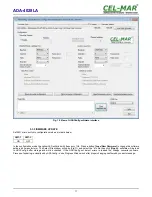
In the configuration mode the yellow LED located by SW1 micro-switch will blink with frequency 1 Hz. Start the ADAConfig software

and make the configuration of transmission parameters for each interfaces and set his visible address from RS485 bus. Firstly should

be set a number of COM port for communication with the converter, then readout the configuration from converter's memory using the
button 

[Read converter configuration]

 and make the proper changes of interfaces setting.

5.2.1. CONFIGURATION OF ADDRESSING MODE

If the option Converter Address will be enabled, on configuration window should be set a proper converter address from range 1 - 255.
If this option is disabled the converter will operate as 

baud rate converter

.

5.2.2. CONFIGURATION OF BAUD RATE AND DATA FORMAT

In both operating modes (addressing / baud rate converter), is possible to set additional transmission parameters for RS485/422 &

Current Loo CLO interfaces separately.

For RS485/RS422 interface:

– baud rate (kbps): 0.3, 0.6, 1.2, 1.8, 2.4, 4.8, 7.2, 9.6, 14.4, 19.2, 28.8, 38.4, 57.6, 76.8, 115.2, 230.4,

– number of data bites: 5, 6, 7, 8,

– control parity: no control, parity control, control of none parity,

– number of stop bits : 1, 2,
– frame spacing – range from 4 to 255 (silence time as frame's end),

For Current Loo CLO interface:

– baud rate (kbps): 0.3, 0.6, 1.2, 1.8, 2.4, 4.8, 7.2, 9.6, 14.4, 19.2,

– number of data bites: 5, 6, 7, 8,

– control parity: no control, parity control, control of none parity,

– number of stop bits : 1, 2,
– frame spacing – range from 4 to 255 (silence time as frame's end),

5.2.3. CONFIGURATION DATA FLOW CONTROL 

In the section 

Data flow control

 for RS485/RS422 interface, can be set:

– signal DE – Off – RS485/RS422 interface operates only in receiving data mode,

– signal DE – Toggle – RS485 interface operates in receiving & transmitting data mode for RS485 bus 2-wires and 4-wires,

– signal DE – On – RS485/RS422 interface operates in RS422 mode,

After configuration the setting should be saved on converter memory by using button 

[Write converter configuration].

Return to work in run mode is made by using SW1 switch (yellow LED blink OFF) as below.

SW1-1

SW1-2

OFF

OFF

10

ADA-4028LA

Содержание ADA-4028LA

Страница 1: ...User manual ADA 4028LA Addressable RS485 422 to 2 WIRE Current Loop CLO Baud Rate Converter 1 io_ada 4028la_v4 02_en ADA 4028LA Copyright 2001 2017 CEL MAR sp j ...

Страница 2: ... 1 CONNECTION OF DEVICE WITH PASSIVE INTERFACE CLO 8 3 3 5 2 CONNECTION OF DEVICE WITH ACTIVE INTERFACE CLO 8 3 3 5 3 CONNECTION OF 4 DEVICES WITH THE PASSIVE CLO INTERFACE 9 3 4 POWER SUPPLY 9 4 ACTIVATION 9 4 1 SIGNALING LEDS 9 4 2 SENSITIVITY SETTING OF CURRENT LOOP CLO RECEIVER 9 5 CONFIGURATION 10 5 1 OPERATION MODE 10 5 2 CONFIGURATION BY THE USE OF ADACONFIG 10 5 2 1 CONFIGURATION OF ADDRES...

Страница 3: ...he device if it is enabled This may result to short circuit and damage the device The device can not be used for applications that determine human life and health eg Medical 1 3 CE LABEL The CE symbol on the device CEL MAR means compatibility with electromagnetic compatibility Electromagnetic Compatibility Directive EMC 2014 30 WE Declaration of Conformity is available by contact with Technical Se...

Страница 4: ...nergy meters like POZYTON LZQM ELSTER A1500 PAFAL and others with possibility of conversion the format and baud rate between connected devices to Current Loop CLO interface and RS485 422 bus The ADA 4028LA is equipped with screw terminal block for connection of RS485 422 Current Loop CLO and power supply Over voltage protection on each RS485 422 lines and Current Loop was made on the base over vol...

Страница 5: ...ount of voltage drop use the powering cable with a suitable section because of the voltage drops use the interference eliminators for powering the converter lay signal cables at a distance of not less than 25 cm away from power cables not powering the converters form the power circuit of devices generate large impulse disturbance like contactors relays inverters 3 1 ASSEMBLING ADA 4028LA converter...

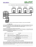
Страница 6: ...US Fig 5 Example connection of ADA 4028LA to RS485 4W 4 wire bus and galvanic separation of SLAVE device 6 ADA 4028LA Rd CLO NC CLO GND USB USB connector RS485 RS422 connector RS485 2W USB connector PC ADA I9140 USB Rx Rx Tx A Tx B Tx A Tx B Rx Rx GND RS485 RS422 connector ADA 4028LA Current Loop connector 5 GND GND 2 Rx 3 Tx RS232 connector DB 9F DCE Screw connector RS485 RS422 RS485 4W bus 9600B...

Страница 7: ...should be used if the distance is over 1000m 9600Bd or 700m 19200Bd transmission the resistor can be necessary if there are problems with the transmission correctness Example connection of Rt are shown on Fig 5 6 Resistor Rt 120 W 5 0 25W of a 2 pc is complete with the device ADA 4028LA 3 3 5 CONNECTION OF CURRENT LOOP DEVICES The connections of SLAVE devices with current loop CLO interface to ADA...

Страница 8: ...ig 8 Example connection of device with active CLO interface to ADA 4028LA 8 ADA 4028LA CLO CLO Current Loop connector V V Power adapter Vss Vss CLO NC CLO GND Tx A Tx B Rx Rx RS485 connector ADA 4028LA ACTIVE Rd Device with passive CLO interface CLO CLO Device with active CLO interface Vss Vss CLO CLO R CLO GND Tx A Tx B Rx Rx Rd Power adapter ADA 4028LA PASSIVE Current Loop connector RS485 connec...

Страница 9: ... Signalling of Power Supply Standard mode RX Signalling of data receiving through the ADA 4028LA converter from Current Loop CLO port TX Signalling of data transmitting from the ADA 4028LA converter through Current Loop CLO port Configuration mode LED by SW1 Blink with frequency 1 Hz signalling of configuration mode see micro switch SW1 setting Firmware update mode LED by SW1 Blinking signalling t...

Страница 10: ...ad converter configuration and make the proper changes of interfaces setting 5 2 1 CONFIGURATION OF ADDRESSING MODE If the option Converter Address will be enabled on configuration window should be set a proper converter address from range 1 255 If this option is disabled the converter will operate as baud rate converter 5 2 2 CONFIGURATION OF BAUD RATE AND DATA FORMAT In both operating modes addr...

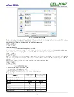
Страница 11: ...Load New Firmware to change the software delivered by manufacturer The Select File window will open Fig 11 and select the bin file then click Open software will be load to ADAConfig buffer storage and will be checked If the ADAConfig not detect errors in loaded file change converter software Process of updating is visualized by ADAConfig in use Progress Window and after proper changing confirmed b...

Страница 12: ...g should be restarted the ADA 4028LA by turning OFF and then ON the power supply The yellow LED will light continuously and the converter will be in Emergency Firmware Update mode Now follow the description in point FIRMWARE UPDATE After successful updating set SW1 micro switch as in table below Yellow LED will be OFF SW1 1 SW1 2 OFF OFF 5 5 FACTORY DEFAULT In case of faulty functioning of ADA 402...

Страница 13: ...erter and data format converter and lets to connect no addressable devices with Current Loop CLO interface transmitting data at different rates and formats of data frame to the RS485 bus in the process of enabling the cooperation with addressable devices Example connection of ADA 4028LA is shown on fig 12 On RS485 bus the frame of protocol for no addressable devices connected to Current Loop CLO p...

Страница 14: ...l ADA 4028LA 1 2 1 24VDC 0 20mA current loop active transmitter 2 1kV 3 way galvanic isolation Current Loop voltage 24VDC 0 20mA active transmitter of Current Loop 1 12VDC 0 20mA active transmitter of Current Loop 2 24VDC 0 30mA active transmitter of Current Loop 3 12VDC 0 30mA active transmitter of Current Loop 4 24VDC 0 20mA passive transmitter of Current Loop 1P 12VDC 0 20mA passive transmitter...

Страница 15: ...op CLO Electrical Parameters Power requirements 10 24 30 V DC Power Cable Recommended length of power cable up to 3m Power 2W Protection from reverse power polarization YES Galvanic Isolation 1kV or 3kV DC between power circuit and RS485 422 signal line Optoisolation 3kV between signal line RS 485 422 and Current Loop Electromagnetic compatibility Resistance to disruptions according to the standar...

Страница 16: ...ata transmission converters with interface RS232 RS485 RS422 USB Current Loop Fibre Optic Converters and Ethernet or Wi Fi Please contact us to tell how you like our products and how we can satisfy you present and future expectation CEL MAR sp j Zakład Informatyki i Elektroniki str Ściegiennego 219C 25 116 Kielce POLAND Tel 48 41 362 12 46 Tel fax 48 41 361 07 70 Web http www cel mar pl en Office ...

Отзывы: