


4.1. SIGNALING LEDS
LED
Description
PWR
Signalling of Power Supply
RUN
RX
Signalling of data receiving through the ADA-4020A converter from Current Loop port
TX
Signalling of data transmitting from the ADA-4020A converter through Current Loop port
Configuration
LED by SW1 Blink with frequency 1 Hz - signalling of configuration mode (see micro-switch SW1 setting)
Firmware update
LED by SW1 Blinking signalling the software data flows to converter.
5. CONFIGURATION
5.1. OPERATION MODE
ADA-4020A converter can operates in a few modes :
–
run,
–
configuration,
–
factory default,
–
emergency firmware update
Those modes can be set by use SW1 located by terminal block RS455/RS422. To set the switch section, should remove terminal
cover marked as SW1 and make the appropriate settings by the use a small, flat screwdriver.
All available adjusting the SW1 switch are shown in table below.
Operation modes
SW1- 1
SW1- 2
Mode
OFF
OFF
Run
ON
OFF
Configuration
OFF
ON
Factory default
Turning OFF and ON the power of the converter, the configuration will be set
to factory default.
ON
ON
Emergency Firmware Update
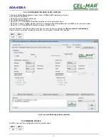
5.2. CONFIGURATION BY THE USE OF ADACONFIG
The configuration of ADA-4040A converter should be done by use of
ADAConfig
software - selling with converter.
To make the configuration, connect converter to computer (see pt. CONNECTION TO PC) and power supply. If after power, on the
front panel is not lit green LED PWR, check the power connection (polarity). If the PWR LED lights, set the section of SW1 switch to
configuration mode as in table below.
SW1-1
SW1-2
ON
OFF
In the configuration mode the yellow LED located by SW1 micro-switch will blink with frequency 1 Hz. Start the ADAConfig software
and make the configuration of transmission parameters for each interfaces and set his visible address from RS485 bus. Firstly should
be set a number of COM port for communication with the converter, then readout the configuration from converter's memory using the
button
[Read converter configuration]
and make the proper changes of interfaces setting.
5.2.1. CONFIGURATION OF ADDRESSING MODE
If the option Converter Address will be enabled, on configuration window should be set a proper converter address from range 1 - 255.
If this option is disabled the converter will operate as
baud rate converter
.
5.2.2. CONFIGURATION OF BAUD RATE AND DATA FORMAT
In both operating modes (addressing / baud rate converter), is possible to set additional transmission parameters for RS485/422 &
Current Loo interfaces separately, like:
– baud rate (kbps) for RS485/RS422: 0.3, 0.6, 1.2, 1.8, 2.4, 4.8, 7.2, 9.6, 14.4, 19.2, 28.8, 38.4, 57.6, 76.8, 115.2, 230.4,
– baud rate (kbps) for Current Loop: 0.3, 0.6, 1.2, 1.8, 2.4, 4.8, 7.2, 9.6, 14.4, 19.2, 28.8, 38.4,
– number of data bites: 5, 6, 7, 8,
– control parity: no control, parity control, control of none parity,
– number of stop bits : 1, 2,
– frame spacing – range from 4 to 255 (silence time as frame's end),
8
ADA-4020A
Содержание ADA-4020A
Страница 15: ...15 ADA 4020A...