Passionate about style
Customer Care Department • The Group Ltd. • Harby Road • Langar • Nottinghamshire • NG13 9HY
T
: 01949 862 012
F
: 01949 862 003
E
: [email protected]
W
: www.cda.eu
HVC70 Four Zone Ceramic Hob
Manual for Installation, Use and Maintenance
Страница 1: ...tyle Customer Care Department The Group Ltd Harby Road Langar Nottinghamshire NG13 9HY T 01949 862 012 F 01949 862 003 E service cda eu W www cda eu HVC70 Four Zone Ceramic Hob Manual for Installation Use and Maintenance ...
Страница 2: ...ORDANCE WITH EC DIRECTIVE 2002 96 EC At the end of its working life the product must not be disposed of as urban waste It must be taken to a special local authority differentiated waste collection centre or to a dealer providing this service Disposing of a household appliance separately avoids possible negative consequences for the environment and health deriving from inappropri ate disposal and e...
Страница 3: ...use by young children or infirm persons unless they have been adequately supervised by a responsible person to ensure that they can use the appliance safely Do not allow young children or infirm persons to use the appliance without your supervision WARNING When correctly installed your product meets all safety requirements laid down for this type of product category However special care should be ...
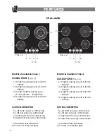
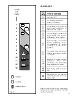
Страница 4: ...ht rear zone 3 control knob 8 Right front zone 4 control knob 9 Residual heat indicators 10 Power on indicator light Electrical insulation Class I COOKING POINTS Fig 1 2 1 Hi light cooking zone Ø 180 mm 1800 W 2 Hi light cooking zone Ø 140 mm 1200 W 3 Hi light cooking zone Ø 180 mm 1800 W 4 Hi light cooking zone Ø 140 mm 1200 W CONTROLS DESCRIPTION 5 Left front zone 1 control knob 6 Left rear zone...
Страница 5: ...t cooking zone Ø 180 x 260 mm 800 2200 W 3 Hi light cooking zone Ø 140 mm 1200 W 4 Double hi light cooking zone Ø 210 120 mm 2200 750 W CONTROLS DESCRIPTION 5 Left front zone 1 control knob 6 Left rear zone 2 control knob 7 Right rear zone 3 control knob 8 Right front zone 4 control knob 9 Residual heat indicators 10 Power on indicator light Fig 1 3 ...
Страница 6: ...hi light cooking zone Ø 180 x 260 mm 800 2200 W 4 Double hi light cooking zone Ø 210 120 mm 2200 750 W 5 Hi light cooking zone Ø 140 mm 1200 W CONTROLS DESCRIPTION 6 Left front zone 1 control knob 7 Left rear zone 2 control knob 8 Central zone 3 control knob 9 Right rear zone 4 control knob 10 Right front zone 5 control knob 11 Residual heat indicators 12 Power on indicator light Fig 1 4 ...
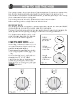
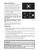
Страница 7: ...rect pans and or wrong pan positioning will cause the temperature lim iter to operate more frequently resulting in a reduction of cooking performance The ceramic surface of the hob allows a fast transmission of heat in the vertical direc tion from the heating elements underneath the ceramic glass to the pans set on it The heat does not spread in a horizontal direction so that the glass stays cool ...
Страница 8: ...ty can be regulated continuously from 0 to 12 max Check that the hob is clean and then switch on by turning the control knob When the hob is working the pilot light will be on By switching on the second element fig 2 4 the surface area of the double and oval hi light zones can be extended For this purpose turn the control knob figs 2 3a 2 3b fully to the right position Fig 2 4 Second element Hi li...
Страница 9: ...ll quantities of liquid sauces eggs To heat bigger quantities to whip creams and sauces vegetables fruits soups Slow boiling i e boiled meats spaghetti soups continuations of steam cooking of roasts stews potatoes For every kind of frying cutlets uncovered cooking i e risotto Browning of meats roasted potatoes fried fish omelettes and for boiling large quantities of water Fast frying grilled steak...
Страница 10: ...knob to the max when you switch the plate on After a short time you will set the control knob to the required position for the cooking You should use pots and pans with flat bases pans with the test mark for glass ceramic hobs are available from specialist shops The diameter of the pan should match that of the cooking plate or be slightly bigger to make the most of the energy Since the cooking sur...
Страница 11: ...an handles should never stand out beyond the kitchen worktop as there is a great danger of knocking the pan over This will also ensure that children cannot reach them Do not use the hob if the glass sur face is broken or cracked in any way Please disconnect the hob from the mains and contact the after sales service Do not lean over the cooking plate when in use Do not lay cooking foil or plastic m...
Страница 12: ...ic surface you should remove it immediately when the surface is still hot by using a scraper to avoid any permanent damage to the surface of the hob available under part no 103138 Do not put articles on the hob which can melt i e plastic aluminium foil sugar sugar syrup mixtures etc Avoid using a knife or other sharp utensil as these may damage the ceramic surface Do not use steel wool or an abras...
Страница 13: ...13 ADVICE FOR THE INSTALLER ...
Страница 14: ... may cause personal injury of damage Always disconnect the cooktop from mains power supply before carrying out any maintenance operations or repairs Fig 3 1a Fig 3 1b Fig 3 1c WARNING We would point out that the adhesive which bonds the plastic laminate to the furniture must withstand temperatures not less than 150 C to avoid delamination The appliance must be housed in heat resistant units The wa...
Страница 15: ...se of the hob fig 3 2 650 mm 50mmmin 50 mm min 500 mm 450 mm Fig 3 3 20 mm min Fig 3 2 the ceramic hob must be kept no less than 50 mm away from any side wall the rear wall must be at least 50 mm from the ceramic hob there must be a distance of at least 650 mm between the hob and any wall cupboard or extractor hood positioned immediately above see fig 3 3 the coatings of the walls of the unit or a...
Страница 16: ...Spread the seal C around the edge of the hob fig 3 5 Put tabs A into the mountings only tighten screws B a few turns Make sure that the tabs are mounted correctly as shown in the figures 3 4 3 5 Put the cooktop into the hole cut into the unit and position it correctly Put tabs A into place tooth D of the tabs should go into the hole Tighten screws B until the cooktop is completely secured Using a ...
Страница 17: ... who is a member of the N l C E l C and who will comply with the l E E and local regulations Before carrying out the connection to the power supply the voltage rating of the appli ance stamped on the appliance identification plate must be checked for correspondence to the available mains supply voltage and the mains electric wiring should be capable of handling the appliance s power rating also in...
Страница 18: ...loured brown must be connected to the terminal marked L Live or coloured Red N B For connections to the mains power supply never use adaptors reductions or multiple power points as these may overheat and catch fire In the event that installation should require modifications to the mains supply wiring sys tem it is recommended that a qualified technician be called to carry out substitution The tech...
Страница 19: ...2 Connect the phase and earth wires to terminal board G according to the diagram in figs 4 2 and 4 3 Strain the feeder cable and block it with cable clamp E by screwing screw D Close the cover C of the terminal board G and block it with the screw A FEEDER CABLE SECTION Type H05VV F or H05V2V2 F or H05RR F 220 240 V 3 x 2 5 mm2 for 60 cm and 80 cm models 220 240 V 3 x 4 mm2 for 90 cm models Connect...
Страница 20: ...ate and that the electrical cable sections can with stand the load specified on the plate The appliance must be connected directly to the mains placing a two pole switch with minimum opening between the contacts of 3 mm between the appliance and the mains The power supply cable must not touch the hot parts and must be positioned so that it does not exceed 50 C above ambient Once the appliance has ...
Страница 21: ...wires to terminal board G according to the diagrams in fig 4 5 Strain the feeder cable and block it with cable clamp E by screwing screw D Close the cover C of the terminal board G and block it with the screw A FEEDER CABLE SECTION Type H05VV F or H05V2V2 F or H05RR F For 60 cm and 80 cm models 220 240 V 3 x 2 5 mm2 380 415 V 3N 5 x 1 5 mm2 380 415 V 2N 4 x 2 5 mm2 For 90 cm models 220 240 V 3 x 4...
Страница 22: ... PE 1 2 3 4 5 PE 1 2 3 4 5 380 415 V 3N 380 415 V 2N N L1 L2 N L1 L3 L2 Fig 4 5 220 240 V 1 2 3 5 4 N L2 PE L1 G C F D E Fig 4 6 1 2 3 5 4 PE N L1 L2 L3 G F D E 380 415 V 3N C 1 2 3 5 4 PE N L1 L2 G F D E 380 415 V 2N C Fig 4 8 Fig 4 7 ...
Страница 23: ...23 ...
Страница 24: ... booklet are given as simply indicative The manufacturer reserves the right considering the characteristics of the models described here at any time and without notice to make eventual necessary modifications for their construction or for commercial needs ...