background image

CD Automation srl 

REVO E-3PH from 25A to 500A 

User’s Manual 

39 


11.4


Analog Outputs 

The REVO E thyristor unit have 1 analog output (0÷10V, 4÷20mA, ecc). 

The output is for retransmitting the average power on the three phases. 


11.4.1


Output 1: Average Power (Terminals 10 and 6 or 10 and 7) 

The average power output is already configured in line with customer requirements that are defined in 

the Order Code. The Order Code is written on the identification label. 

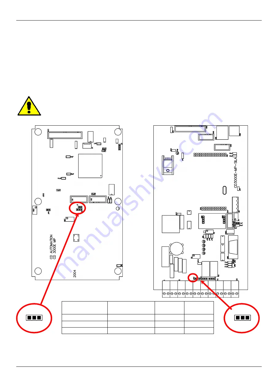
However, if you wish to change the average power output (ex. from 0÷10V to 4÷20mA) proceed as 

follows: 


Caution:

 this procedure must be performed only by qualified persons


Size S09 

Size S11/S13/S14 


JP2

C B A


Type 

Output features 

P097





Jumper 

0

10V (default) 

20mA Max 

A-B 

0

20mA 

500

 Max 

B-C 

4

20mA 

500

 Max 

B-C 


JP21

C B A


Setting the Output Value 

The parameter P104 



 allows to set the full scale value to have the maximum output, 

for example if you use an indicator with full scale 50Kw set the parameter P104 



 = 50. 


Содержание REVO E 3PH

Страница 1: ... r l Via Picasso 34 36 20025 Legnano MI ITALY Tel 39 0331 577479 Fax 39 0331 579479 E Mail info cdautomation com WEB www cdautomation com REVOE 3PH BASIC Thyristor Unit USER S MANUAL Rev 10 2014 00004 from 25A to 600A ...

Страница 2: ......

Страница 3: ......

Страница 4: ...5 6 3 Removing the cover 16 7 Wiring instructions 17 7 1 Wiring details 17 7 2 Power Terminals 19 7 3 Command Terminals Size S09 20 7 4 Diagram of control connection Size S09 21 7 5 Command Terminals Size S11 S13 S14 22 7 6 Diagram of control connection Size S11 S13 S14 23 8 Power output features 24 8 1 Derating curve 24 8 2 Cooling fans 24 9 Led status and Alarms 25 9 1 LED Status Table 25 9 2 Cr...

Страница 5: ...ronic boards 37 11 2 Supply the Electronic Board 37 11 3 Analog Inputs 38 11 4 Analog Outputs 39 11 5 Digital Input 40 11 6 Digital Output 41 11 7 PG Connector 42 12 Internal Fuse 43 12 1 Fuse Code 43 13 Maintenance 44 13 1 Fans 44 13 2 Maintenance 44 13 3 Repairing procedure 44 13 4 Warranty condition 44 ...

Страница 6: ...ows the qualified people to work in safety Protection Protection Protezione The unit have IP20 protection rating as defined by the specific international Is necessary consider the place of installation Earth Terre Messa a terra For safety the Thyristor unit with isolated heat sink must be connected to earth Earth impedance should be correspondent to local earth regulation Periodically the earth ef...

Страница 7: ...ll suggestions contained in this manual are respected In respect to a good Engineering practice all inductive loads like solenoids contactor coils should have a filter in parallel Emissions Emission Emissioni All solid state power controllers emit a certain amount of radio frequency energy because of the fast switching of the power devices The CD Automation s Thyristor unit are in accord with the ...

Страница 8: ...ly solution to control transformers and special loads that change resistance with temperature and with age 2 1 Advantages compared with analog thyristor unit REVO E is an universal Thyristor unit designed to control resistive or inductive loads including three phase transformers The electronic circuit is completely digital and is based on a powerful microprocessor with high performance that allow ...

Страница 9: ... only to modify the ordered configuration Anyway we suggest to check the unit on the machine with the Test unit section For install the software launch the program and follow the instructions on the screen To connect the unit at the PC it s necessary use the USB TTL converter connected between the unit and the USB port of the PC USB TTL converter need a driver to work properly you can find it from...

Страница 10: ... load voltage is equal or less than the MAX voltage of REVO E see par 4 2 Verify the Order Code see par 5 2 3 Verify the Installation see par 6 4 Verify the Diagram of control connection All auxiliary connections must be done in line with wirings on this manual Verify that there isn t a short circuit on the load see par 7 4 5 Supply the Electronic boards see Order Code 6 If not specified in the Or...

Страница 11: ... to phase I Nominal current of the load P Nominal power of the load 4 1 3 Delta wiring with resistive load V P I 73 1 V Nominal voltage phase to phase I Nominal current of the load P Nominal power of the load 4 1 4 Delta wiring with inductive load cos V P I 73 1 V Nominal voltage phase to phase I Nominal current of the load P Nominal power of the load 4 1 5 Open Delta wiring with resistive load V ...

Страница 12: ...sure that the Thyristor unit have not damages If the product has a fault please contact the dealer from which you purchased the product The identification s label give all the information regarding the factory settings of the Thyristor unit this label is on the unit like represented in figure Verify that the product is the same thing as ordered see par 5 2 ...

Страница 13: ...CD Automation srl REVO E 3PH from 25A to 500A User s Manual 13 5 2 Order Code ...

Страница 14: ...net maintain the air circulation like represented in figure Sometimes is necessary installing a fan to have better air circulation 6 1 Environmental installation conditions Ambient temperature 0 40 C at nominal current Over 40 C use the derating curve see par 8 1 Storage temperature 25 C to 70 C Installation place Don t install at direct sun light where there are conductive dust corrosive gas vibr...

Страница 15: ...ing holes Size S09 25A 75A Weight 5kg 290mm 96mm 104mm 5mm 7mm 440mm 270mm 137mm Size S11 100A 150A Weight 10 5kg 97mm 410mm 97mm 7mm 12mm 440mm 270mm 262mm Size S13 225A Weight 18kg 410mm 222mm 222mm 7mm 12mm 460mm 270mm 262mm Size S14 300A 600A Weight 22 5kg 222mm 222mm 490mm 7mm 12mm ...

Страница 16: ...emoving the cover Size S09 Remove the screw if present Open the unit Screw Open Size S11 Remove the screw if present Remove the plastic cover Open the unit Screw Screw Open Size S13 S14 Remove the screw Remove the plastic cover Open the unit Screw Screw Screw Screw Open ...

Страница 17: ...ilter Use shielded bipolar cables for all the input and output signals The signal cables must not be near and parallel to the power cables Local regulations regarding electrical installation should be rigidly observed For safety connect the heat sink to the earth with his terminal 7 1 Wiring details Use copper cables and wires rated for use at 75 C only 7 1 1 Power cable torque suggested Current C...

Страница 18: ...5 3 16 6 125A S11 50 1 50 1 16 6 150A S11 70 1 0 70 1 0 16 6 225A S13 120 4 0 120 4 0 25 4 300A S14 2 x 70 2 x 1 0 2 x 70 2 x 1 0 50 1 350A S14 2 x 95 2 x 3 0 2 x 95 2 x 3 0 50 1 400A S14 2 x 95 2 x 3 0 2 x 95 2 x 3 0 50 1 450A S14 Bus Bar 30 x 6 mm Bus Bar 30 x 6 mm 70 1 0 500A S14 Bus Bar 60 x 4 mm Bus Bar 60 x 4 mm 70 1 0 600A S14 Bus Bar 60 x 4 mm Bus Bar 60 x 4 mm 70 1 0 7 1 3 Cable dimension...

Страница 19: ...cting the unit check that power and control cables are isolated from voltage sources Terminal Description L1 Line Input Phase 1 L2 Line Input Phase 2 L3 Line Input Phase 3 T1 Load Output Phase 1 T2 Load Output Phase 2 T3 Load Output Phase 3 Size S09 L1 L2 L3 T1 T2 T3 Size S11 L1 L2 L3 Size S13 L1 L2 L3 Size S14 L2 L1 L3 ...

Страница 20: ...ee par 11 2 3 Not used 4 Isolated output 12Vdc MAX 20mA 5 GND for Digital Input 6 Output 10Vdc MAX 5mA 7 GND for Analogue Input 8 Analogue Input 1 Primary See par 11 3 9 Not used 10 Analogue Output 1 Power See par 11 4 11 Not used 12 Not used 13 Output relay Run Max 500mA 125Vac 14 Common of the contact relay Run 15 NPN Output 1 Critical Alarm 12Vdc max 20mA 16 NPN Output 2 Configurable 12Vdc max ...

Страница 21: ...lectromagnetic circuit breaker or by fuse isolator 2 Use an appropriate external transformer based on the voltage supply of the electronic board see the identification label 3 The coil contactor the relays and other inductive loads must be equipped with opportune RC filter 4 Before give the Start command supply the auxiliary voltage Load Type T1 T2 T3 T1 T2 T3 L1 L3 L2 T1 T2 T3 T1 T2 T3 N Delta Op...

Страница 22: ...d 4 Isolated output 12Vdc MAX 20mA 5 GND for Digital Input 6 Output 10Vdc MAX 5mA 7 GND for Analogue Input 8 Analogue Input 1 Primary See par 11 3 9 Not used 10 Analogue Output 1 Power See par 11 4 11 Output relay Conf Max 500mA 125Vac 12 Common of the contact relay Conf 13 Output relay Run Max 500mA 125Vac 14 Common of the contact relay Run 15 NPN Output 1 Critical Alarm 12Vdc max 20mA 16 NPN Out...

Страница 23: ...by electromagnetic circuit breaker or by fuse isolator 2 Use an appropriate external transformer based on the voltage supply of the electronic board see the identification label 3 The coil contactor the relays and other inductive loads must be equipped with opportune RC filter 4 Before give the Start command supply the auxiliary voltage Load Type T1 T2 T3 T1 T2 T3 L1 L3 L2 T1 T2 T3 T1 T2 T3 N Delt...

Страница 24: ...0 1600 1600 450 5000 15 108000 47 70 540 3000 225A 330 600 1600 1600 300 5000 15 109000 47 70 810 3000 300A 330 600 1600 1600 300 5000 15 125000 47 70 1080 3000 350A 330 600 1600 1600 200 7900 15 300000 47 70 1260 3000 400A 330 600 1600 1600 200 8000 15 306000 47 70 1440 3000 450A 330 600 1600 1600 1000 15000 15 1027000 47 70 1620 2500 500A 330 600 1600 1600 1000 15000 15 1027000 47 70 1800 2500 6...

Страница 25: ...LED that indicates the state of the Electronic cards LED For All size STATUS DESCRIPTION AUX The power supply is not connected or fault on the electronic board Fault on the electronic board Electronic board is OK All ON No alarm In Alarm Critical Alarm SC SCR OK SCR short circuit HB Laod OK Load Fault Current limit active OFF ON Lampeggiante ...

Страница 26: ...gital input Reset Alarm see par 11 5 9 2 2 External Alarm This critical alarm is active when the Digital input 4 is configured like External Alarm and is activated For restart the thyristor unit you must disarm the external alarm When the problem is solved before to restart is necessary use the digital input Reset Alarm see par 11 5 9 2 3 Heat sink Over temperature This critical alarm is active wh...

Страница 27: ...larm is active when the load current decrease under the threshold set on the parameter P066 The Heater Break alarm could be active also if there are a wrong wiring of the load When the problem is solved is necessary use the digital input Reset Alarm see par 11 5 The Heater Break alarm to work properly must have an input signal more then 25 of the nominal current value Caution In the first start an...

Страница 28: ...ingle Cycle it s the faster zero crossing switching method in relationship of the power demand from a temperature regulator or from an external signal With input signal at 25 the output is one cycle ON and three cycles OFF With input signal at 50 the output is one cycle ON and one cycle OFF With input signal at 75 the output is three cycles ON and one cycle OFF With input signal at 76 the output i...

Страница 29: ... P019 H13 100 Maximum Output R W P024 H18 0 Setpoint Ramp Up Sec R W P025 H19 0 Setpoint Ramp Down Sec R W P116 H74 V Load Operative load voltage V R W P119 H77 I Load Load nominal current A R W SETUP MENU Parameter Name Value Description UM Mode P023 H17 0 Firing Type R W P066 H42 20 HB sensitivity R W P070 H46 1 Feed back selection R W P083 H53 1 Burst Firing Cycles Not used in Phase Angle Cycle...

Страница 30: ...V 100 ON OFF LOAD VOLTAGE V 75 50 25 10 2 1 Soft Start with Burst Firing S BF This is an additional function to the Burst Firing The unit start in phase angle mode with a ramp starting from zero up to the full tension in the cycles number set in the parameter P084 When the ramp is over the thyristor unit will stay in conduction at full voltage up to the end of cycles of burst The S BF firing is us...

Страница 31: ...W P024 H18 0 Setpoint Ramp Up Sec R W P025 H19 0 Setpoint Ramp Down Sec R W P116 H74 V Load Operative load voltage V R W P119 H77 I Load Load nominal current A R W SETUP MENU Parameter Name Value Description UM Mode P023 H17 0 Firing Type R W P066 H42 20 HB sensitivity R W P070 H46 1 Feed back selection R W P083 H53 8 Burst Firing Cycles Not used in Phase Angle Cycles R W P084 H54 P083 Ramp Cycles...

Страница 32: ...rtz Lamp The only disadvantage with phase angle is the possible generation of interferences that however can be reduced with opportune filters VOLTAGE SUPPLY V 100 ON OFF LOAD VOLTAGE V 75 50 25 10 3 1 Soft Start with Phase Angle S PA This is an additional function to the Phase Angle The firing angle of the thyristor increase or decrease up to the final setpoint value The Soft start ramp is an imp...

Страница 33: ...P024 H18 0 1000 Setpoint Ramp Up Sec R W P025 H19 0 1000 Setpoint Ramp Down Sec R W P116 H74 V Load Operative load voltage V R W P119 H77 I Load Load nominal current A R W SETUP MENU Parameter Name Value Description UM Mode P023 H17 1 Firing Type R W P066 H42 20 HB sensitivity R W P070 H46 1 Feed back selection R W P083 H53 Burst Firing Cycles Not used in Phase Angle Cycles R W P084 H54 Ramp Cycle...

Страница 34: ...urrent Zero Crossing Voltage Voltage Voltage Current Delay angle 0 to 100 0 Zero Crossing Voltage For understand the Delay Triggering firing we have represented the waves generate by vectors that rotates in counterclockwise Without Delay Triggering With Delay Triggering y V1 I1 V3 I3 I2 V2 x i2 i1 i3 y V1 I1 V3 I3 I2 V2 x i2 i3 Delay Angle Without delay at zero crossing when V1 is to zero projecte...

Страница 35: ... Ramp Up Sec R W P025 H19 0 1000 Setpoint Ramp Down Sec R W P116 H74 V Load Operative load voltage V R W P119 H77 I Load Load nominal current A R W SETUP MENU Parameter Name Value Description UM Mode P023 H17 2 Firing Type R W P066 H42 20 HB sensitivity R W P070 H46 1 Feed back selection R W P083 H53 8 Burst Firing Cycles Not used in Phase Angle Cycles R W P084 H54 0 Ramp Cycles of Burst Not used ...

Страница 36: ...ut The feed back defines the Control Mode It s possible to have V Voltage feed back The input signal is proportional to the output voltage This means that input signal becomes a voltage demand This control mode compensates the voltage fluctuation of the incoming line supply I Current feed back The input signal is proportional to the current output This means that input signal becomes a current dem...

Страница 37: ...requires a voltage supply for the electronic boards This voltage is used also to supply the internal fans The consumption is 20VA max at this you must add the consumption of the internal fans see par 8 2 The voltage supply for the electronic boards is configured in line with customer requirements that are defined in the Order Code The Order Code is written on the identification label Warning Befor...

Страница 38: ... ex from 0 10V to 4 20mA proceed as follows Size S09 Size S11 S13 S14 JP6 Type Input features Jumper 0 10V default Impedance 40K Open POT Impedance 10K min Open 4 20mA Impedance 500 Close JP8 Primary Input calibration procedure When you change the hardware setting is necessary make the Input calibration procedure To make the Input calibration procedure follow these steps Give the power supply With...

Страница 39: ...d in the Order Code The Order Code is written on the identification label However if you wish to change the average power output ex from 0 10V to 4 20mA proceed as follows Caution this procedure must be performed only by qualified persons Size S09 Size S11 S13 S14 JP2 C B A Type Output features P097 Jumper 0 10V default 20mA Max 0 A B 0 20mA 500 Max 0 B C 4 20mA 500 Max 1 B C JP21 C B A Setting th...

Страница 40: ...l 19 The Calibration input activates the Calibration procedure that is necessary if you use the Burst Firing BF or the Heater break alarm see par 9 4 11 5 4 Configurable Input Terminal 20 This digital input is configured by the parameter P103 and could perform different functions Additional Reset Alarm This function is the same of the Reset Alarm command Setpoint zero This function forces the outp...

Страница 41: ... the P113 The standard contact used for this output is normally open NO but is possible change the contact type Size S11 S13 S14 Type Jumper NC A B NO standard B C JP23 C B A 11 6 2 Run Relay Terminals 13 and 14 This digital output is used to control the main contactor when the thyristor unit is in run the output is active and the contact is closed 11 6 3 Critical Alarm Terminal 15 This digital ou...

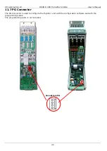
Страница 42: ...3PH from 25A to 500A User s Manual 42 11 7 PG Connector The PG Connector is used to configure the thyristor unit with the configuration software and with the programming cable The programming cable is not included Connettore PG ...

Страница 43: ... 100 2 x 100 10540 660 3 100A S11 20 282 20 180 180 16320 660 3 125A S11 20 282 20 180 180 16320 660 3 150A S11 20 282 20 250 250 35200 660 3 225A S13 20 559 20 315 315 61600 660 3 300A S14 FU450FMM 450 84000 660 3 350A S14 FU550FMM 550 193500 660 3 400A S14 FU550FMM 550 193500 660 3 450A S14 FU700FMM 700 378000 660 3 500A S14 FU700FMM 700 378000 660 3 600A S14 FU700FMM 700 378000 660 3 Caution Th...

Страница 44: ...cy of these operations depends on the atmospheric local pollution Check also that the screw of the power terminals and earth terminals are shut correctly see Diagram of control connection 13 3 Repairing procedure Phone to CD Automation Explain to Service Engineer the problem because sometimes it can be solved with a phone call If this is not possible ship the unit to CD Automation or to your distr...

Отзывы: